TAGGED: rpm-and-torque, transient, transient-structural
-
-
November 14, 2022 at 11:33 am
-
November 14, 2022 at 2:23 pm
peteroznewman
SubscriberWhat is the purpose of simulating the self loosening of this nut? What do you plan to do with the simulation?
-
November 15, 2022 at 6:47 am
Andi Ko
SubscriberI need to know the loosening torque and final clamp force of the locknut
-
-
November 15, 2022 at 11:52 am
peteroznewman
SubscriberNo torque is applied to the nut when transverse vibration loosens it. The final clamp force depends on the level of the transverse vibration and the duration of the vibration.
-
November 15, 2022 at 12:19 pm
Andi Ko
Subscriberyes, my simulation project is similar to junker test machine actually
-
-
November 16, 2022 at 12:42 am
peteroznewman
SubscriberWhat is the purpose of creating a simulation of this? Do you have a physical junker test machine to validate the simulation against?
-
November 18, 2022 at 12:40 am
Andi Ko
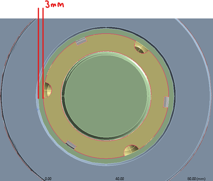
Subscriberyes, I'm struggling with the rpm setting and contact part between the moving plate and the ring. the rpm must be around 800-1500, moving plate and ring clearance is 3mm (I don't know what kind of contact should I use for this). do you have any idea?
-
-
November 18, 2022 at 9:58 am
peteroznewman
SubscriberThe image you show has a cylinder with a pin and a link connecting to a plate. I assume the cylinder is what has the RPM setting, that the pin is eccentric from the rotation axis and that the gray plate is what will be set into a tranvserse vibration. Is that right?
If you are interested in simulating the nut loosening, and not the mechanism that causes the transverse vibration, delete the link, eccentric pin and rotating cylinder. Apply the intended motion directly to the end face of the top plate of the bolted connection.
RPM = revolutions per minute but the simulation uses seconds, so you will divide by 60. You just deleted the rotating shaft, but the relevant information was the radial dimension of the center of the pin to the rotation axis. That number is the amplitude of the vibration, A.
You need to define the boundary condition of the end face. Let's assume the face has a normal along the X axis. Apply a Displacement boundary condition to that face that has the form x = A*sin(wt) where w is calculated from the RPM and t is time in seconds.
Let's take the example of 1200 RPM = 20 revolutions/second.
You have to know if the sin() funtion takes input in degrees or radians. If the sin() function takes input in degrees, there are 360 degrees/revolution so that means w = 7200. If the sin() funtion takes input in radians, there are 2pi radians/revolution so that means w = 40pi.
This is a transient dynamics problem. Your choices are Transient Structural, Explicit Dynamics or LS-Dyna. Do you have access to all these? Use either Explicit Dynamics or LS-Dyna. When you choose one, look up if the sin() function takes input in degrees or radians.
In Explicit Dynamics, frictional contact is automatically created between all bodies.
-
November 19, 2022 at 1:11 am
-
November 19, 2022 at 9:43 am
peteroznewman
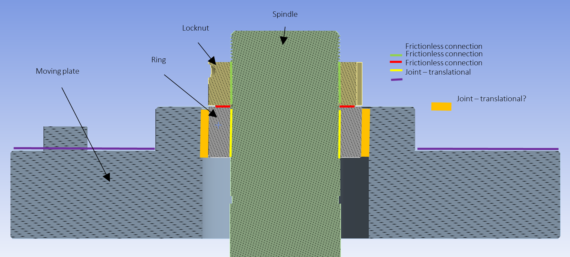
SubscriberI don't understand which part you are talking about. Please show an exploded view. In the exploded view, label all the parts.
-
November 20, 2022 at 9:04 am
-
-
November 20, 2022 at 8:56 am
-
November 20, 2022 at 4:55 pm
peteroznewman
SubscriberPlease show all the boundary conditions. In the image in your original post, there is a boundary condition marked with an A. What is that?
Is the spindle threaded through the length shown above?
Is the Ring threaded onto the spindle or is there a clearance hole in the ring that the spindle passes through?
How is the Ring physically connected to the Moving Plate? (not how you modeled it, how it actually is).
All the contact in the model that is part of the threads or the interfaces that are being clamped must be Frictional! If there is no friction, a locknut will immediately loosen. Frictionless contact can only be used to represent roller bearing supported slides that are not modeled.
A traditional junker test on a threaded fastener has a fastener with a head that passes through a upper plate with a clearance hole in it and into a threaded hole in a lower plate. The faster clamps the interface surfaces of the two plates together. What you are showing is very different to that.
Please show the load path for this assembly. If the spindle is threaded into the ring,
What is turned to tighten the threaded fastener before the locknut is turned?
-
November 21, 2022 at 7:21 am
Andi Ko
Subscriber- In the original image, A is fixed support and B is joint load - rotational velocity (but it turns out that the velocity can only reach 100 rpm, maybe my analysis setting is wrong, so I don't use this method)
- Now, there are three boundary conditions I set. fixed support, moment load (locknut), joint load-displacement (moving plate will move 3.5mm every 0.025s) so in 1 sec there are 40 steps (displacement)
- No, the spindle only threaded for and until the locknut
- No, the ring and spindle have no thread
- In the actual machine, the ring placed on another support below the ring
- I get it, I'll change to frictional
- first locknut is tightened then the plate hits the ring to cause a vibration
-
-
- The topic ‘Transverse Vibration Self-Loosening Nut’ is closed to new replies.


-
4893
-
1587
-
1386
-
1242
-
1021

© 2026 Copyright ANSYS, Inc. All rights reserved.


