TAGGED: -Photonic-crystal, resonance, transmittance
-
-
September 25, 2023 at 8:33 am
Muhammad Danial Haziq Azizan
SubscriberHye,
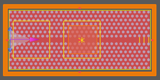
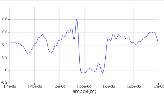
- In the transmittance spectrum, a resonant peak should be triggered when I design PhC including the cavity. But, when I do the simulation, there is no resonant peak. So, I cannot calculate the Q-factor instead of using the Q-analysis since I need to prove the Q-factor based on the transmittance spectrum.
- In what case does the FDTD need in 2D and 3D?


- From this figure, I cannot find any difference when I do the mode cavity by shifting holes 3,6 and 9nm. How to prove?

-
September 25, 2023 at 5:44 pm
Guilin Sun
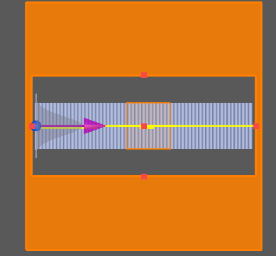
Ansys EmployeeIt seems you only changed the property of 3 holes. this might not be enough to create strong resonance. They are at the end of simulation curretly. You may need to shift the source and the time monitor to right, and set the time monitor in the region of strong resonance.
In general we should use 3D FDTD. The only exception is, the 3rd dimension is very long, in theory it will be infinitely long if 2D is used.
In general you will need to use override mesh to make sure the discrete mesh is also periodic.
-
September 27, 2023 at 12:59 am
Muhammad Danial Haziq Azizan
Subscribermeans that I need to change the position of the source near my PhC cavity? Yes. I use 2D FDTD cause it takes time to simulate.
-
Viewing 2 reply threads
- The topic ‘Transmittance Spectrum with Resonant Wavelength’ is closed to new replies.
Innovation Space


Trending discussions


Top Contributors


-
4678
-
1565
-
1386
-
1241
-
1021
Top Rated Tags


© 2025 Copyright ANSYS, Inc. All rights reserved.
Ansys does not support the usage of unauthorized Ansys software. Please visit www.ansys.com to obtain an official distribution.


