-
-
January 19, 2022 at 6:05 pm
mkalel
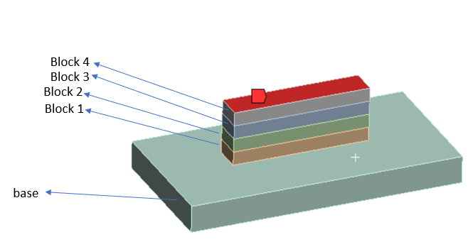
SubscriberI am trying to do a thermal simulation and stress analysis in 3D printed parts. I have 4 blocks and the bottom is the printing base. Since the 3d printer prints 1 layer/block at a time. How can I set up the transient simulation like at t=1 sec for the first block and t=2 sec for the second block and t=3 sec for the third block and so on?
the top layer is at 200 degree celsius.
Also is it possible to see the temperature change for each layer at a specific time? or maybe the animation to see how the temperature is varying while printing every layer.?
Any help or idea will be appreciated.
January 25, 2022 at 10:52 pmJohn Doyle
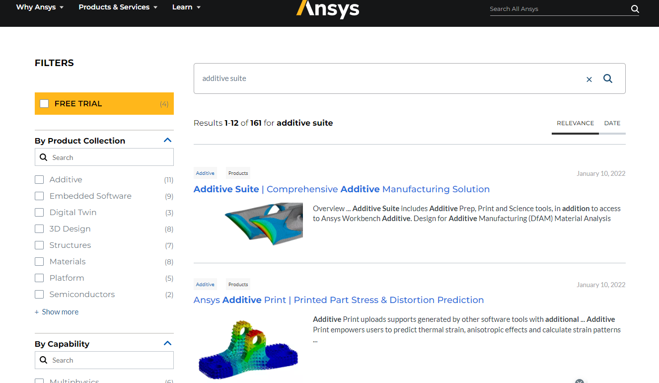
Ansys EmployeeIt appears you are trying to do this manually in WB-Mechanical. While this can be done, I would strongly encourage you to explore the Additive Suite on our ANSYS Website (www.ansys.com). There is an option for a free trial version. The automation that comes with this module is worth the upfront investment in time. It will pay off in the end, when your applications become more complex.
January 26, 2022 at 1:16 ammkalel
SubscriberHello JJdoyle I appreciate your help in answering my question.
I am working with the academic version of ANSYS. so Am I making it harder simulation by doing manually in the workbench? Is there any specific software approach inside the ANSYS to perform such kind of simulation?
Thanks,
mkalel
January 26, 2022 at 5:39 pmJohn Doyle
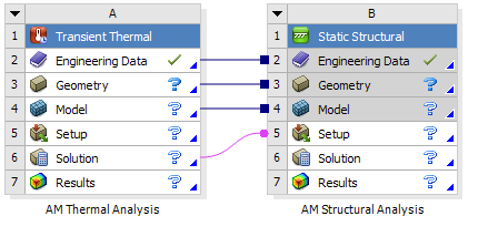
Ansys EmployeeDoes your academic license support Element Birth (EALIVE) and Death (EKILL)? Mechanical AM uses these APDL commands in macros under the hood, in a weakly coupled sequential transient thermal - static structural. This represent the basic strategy used in Mechanical AM. There is an AM course available on the Ansys Learning Hub that goes into a lot more detail.
 If you have access to the MAPDL Commands Manual, you could also look up APDL commands like AMTYPE, AMBUILD, AMENV,...etc to get an idea as to what the code is doing for an AM simulation. Although without an AM license, you will not be able to execute these AM macros directly.
You might still be able to use EKILL/EALIVE. To do this manually in Mechanical, create a multi-bodied part and kill all but first layer. Then thru a series of restarts, birth each layer into the model during a transient thermal. Feed these thermal results into a static structural analysis and perform same EKILL/EALIVE scheme. There are several assumptions that go into this simplified approach. I summarize them below.
Thermal and structural physics are uncoupled (weak coupling)
Mechanical AM does not follow the laser beam (we use a hole layer at a time)
Mechanical AM assumes the thermal effects in build direction, normal to base plate, are more relevant than the in-plane effects
Lumped layered approach is used where several powder layers are lumped to one FE layer (due to the computational effort). One FEA element might represent 10-20 powder deposition layers. The simulation time is not equal to real world time. The reason is that temperature is used as a controlled input. Time is then used to ensure thatthe total energy developed for each lumped layer is consistent with the actual energy to accomplish the build, based on various AM build specifications (laser size and speed, layer size, heat capacityetc) so that the result will be correct at the end. I am not sure how you would do this last part manually, except maybe for the simplest problems.
January 26, 2022 at 6:01 pmmkalel
SubscriberHello JJ Doyle Thank you once again for your help.
Yes, I believe our academic version support EALIVE and EKILL command. I usually use ANSYS software at the University's computer. So, I think our university has a good version of ANSYS with enough licence to support those APDL.
This is definitely going to help me during my simulation. It also helped me understand some of the content and technique that is used to get a correct result. I assume once I start the simulation, it is going to be a complex simulation and there would be a lot of things to play with. Your answer will help me to figure out those problems.
For now, I will give it a try to run a simulation. I will definitely get in touch with you If I get into some problem. Once again thank you for helping me and for your time.
Best Regards,
Mukesh Kalel
January 27, 2022 at 3:10 pmbombsaabb
SubscriberHello Guys,
I am working on a kind of similar situation. So my objective is to do Thermal and Structural Analysis of a LPBF Method, that as mentioned by MR JJDOYLE; I would like to do the first layers of thick mesh and then go ahead with finer mesh to see how it can compute to a certain thickness, as Laser works over a 30╬╝m layer height, but I can assume to work with a higher layer thickness. The Problem I am facing is how to provide ANSYS with the path to continue with the heat.
I was thinking to do just ONE layer at first but how should I give input of the path information, as the file which is readable to the machine is .slm, I can transfer it to .stl or .Gcode. Please help me with this transfer of information or does it need to be coded, if Yes, could your please say how? I guess how do tell ANSYS that activate/birth the elements of this coordinate and then do the same according to the Gcode file.
After that how do I activate the elements using APDL, I tried to look for the Element Birth and Death but that is each element solving as each time step, I want to give code something to do a repeat process, if there is any tutorial/discussion with the code information and detailed learning please help me with that.
Stay Safe
Best Regards
Bomb
January 28, 2022 at 7:45 ammkalel
SubscriberHello bomb I have no idea about controlling the first layer thickness manually in APDL coz I am new to that. But I can say there is a additive manufacturing tutorial on ANSYS 2021 Help guide. I went through that tutorial yesterday and found out that there is one very similar LPBF technique where you can play with the AM process setting . I guess thats the option you can play with to print the first layer as you want .
thanks Mukesh
January 28, 2022 at 8:59 ambombsaabb
SubscriberHey Mukesh,
I have been unable to find any tutorial. could you help me wiht some more details or keywords.
Also I'm thinking to use Ekill and Ealive approach with the elements, doing each layer with named selection. Any suggestion to do that? Also, I am finding it difficult to use APDL commands to fulfil my purpose, a little guide would be very helpful.
BR
Bomb
January 28, 2022 at 10:55 pmmkalel
Subscriber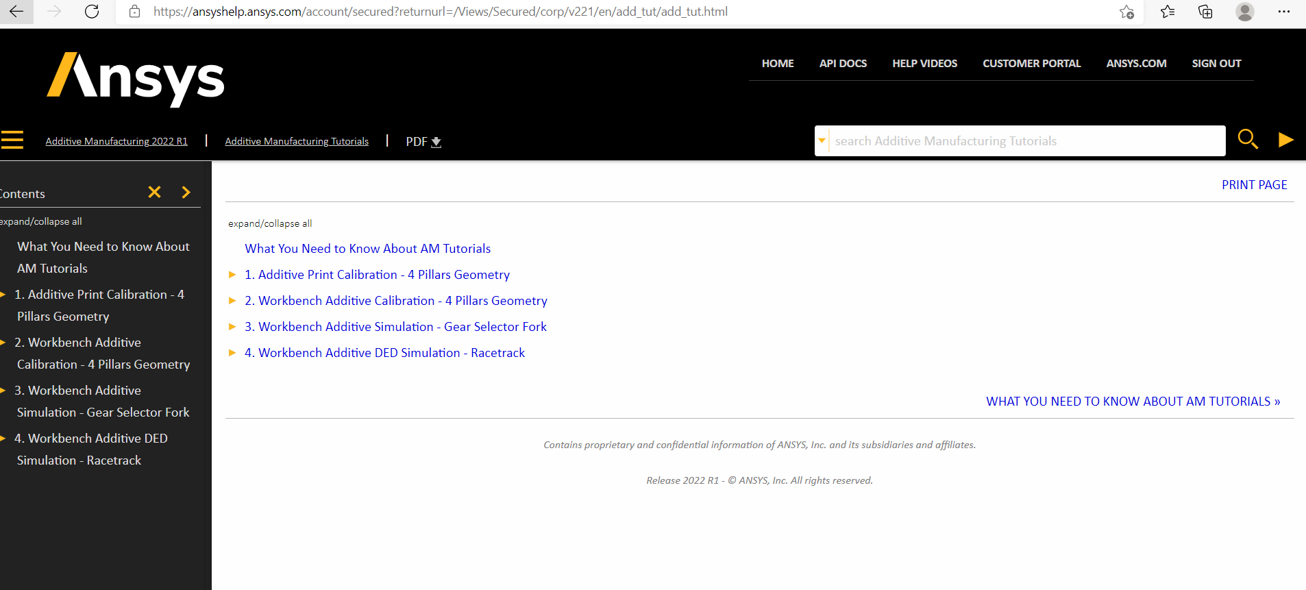 Hello Bomb
Sorry about the late reply. I am very new to the apdl command so I actually have no idea about how to use the ealive and ekill command. But i am watching some of the youtube videos to learn the APDL command. I am planning to post a discussion about how to use those apdl. I have found any specific video of using APDL yet.
But, As suggested in the last reply, The tutorial I was following could help you I believe i have taken a screenshot of it. I guess you can able to findout from there.
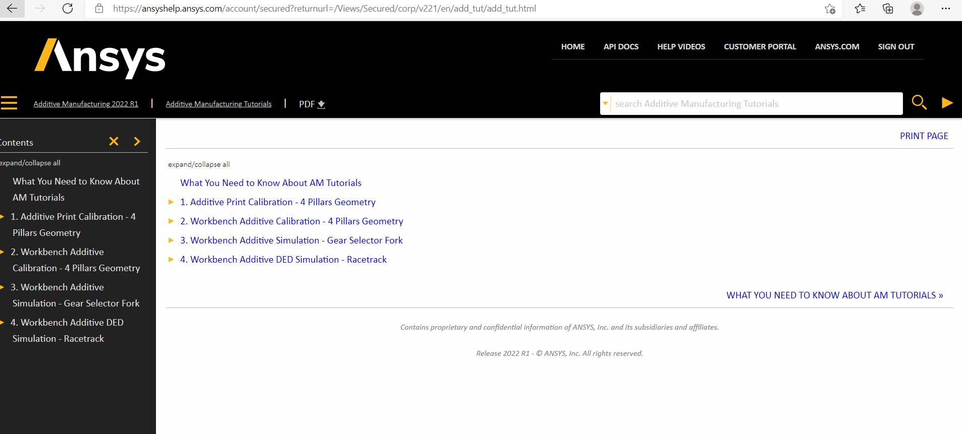 thanks
January 28, 2022 at 11:00 pmmkalel
SubscriberI am planning to put a discussion about how to use APDL technique on this kind of simulation. I hope its gonna help us both if somebody answer
February 7, 2022 at 4:24 pmmkalel
Subscriber
I was reading some the guide and practicing some of the videos. I also read your last reply. Since I am trying to simulate 3D printing process which more like (FDM) where the melted filament comes out from the nozzle to create a part (bolck in my model). So I am not using laser in my project .so Is it good idea to use AM process in a workbench for this kind of thermal and structural simulation?
thanks
mkalel
Viewing 10 reply threads- The topic ‘Transient thermal and stress analysis in a 3D printed parts’ is closed to new replies.
Ansys Innovation SpaceTrending discussionsTop Contributors-
3492
-
1057
-
1051
-
965
-
942
Top Rated Tags© 2025 Copyright ANSYS, Inc. All rights reserved.
Ansys does not support the usage of unauthorized Ansys software. Please visit www.ansys.com to obtain an official distribution.
-
The Ansys Learning Forum is a public forum. You are prohibited from providing (i) information that is confidential to You, your employer, or any third party, (ii) Personal Data or individually identifiable health information, (iii) any information that is U.S. Government Classified, Controlled Unclassified Information, International Traffic in Arms Regulators (ITAR) or Export Administration Regulators (EAR) controlled or otherwise have been determined by the United States Government or by a foreign government to require protection against unauthorized disclosure for reasons of national security, or (iv) topics or information restricted by the People's Republic of China data protection and privacy laws.

