-
-
November 24, 2021 at 8:07 pm
OROI
SubscriberHi
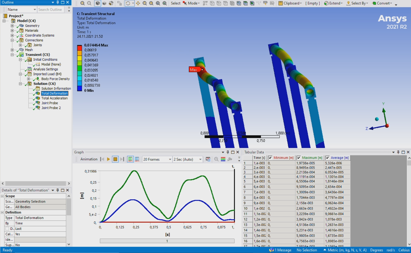
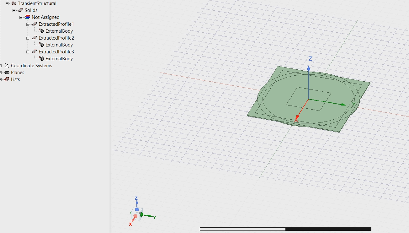
I'm simulating short circuit force of busbar. I noticed that, busbar does not vibrate like it should, after there is no electromagnetic force applied. Busbar and steel supports bend only positive side but never go to the negative, its just dampens before it goes to negative side. How to make it busbar behave more realistic?
November 24, 2021 at 10:21 pmpeteroznewman
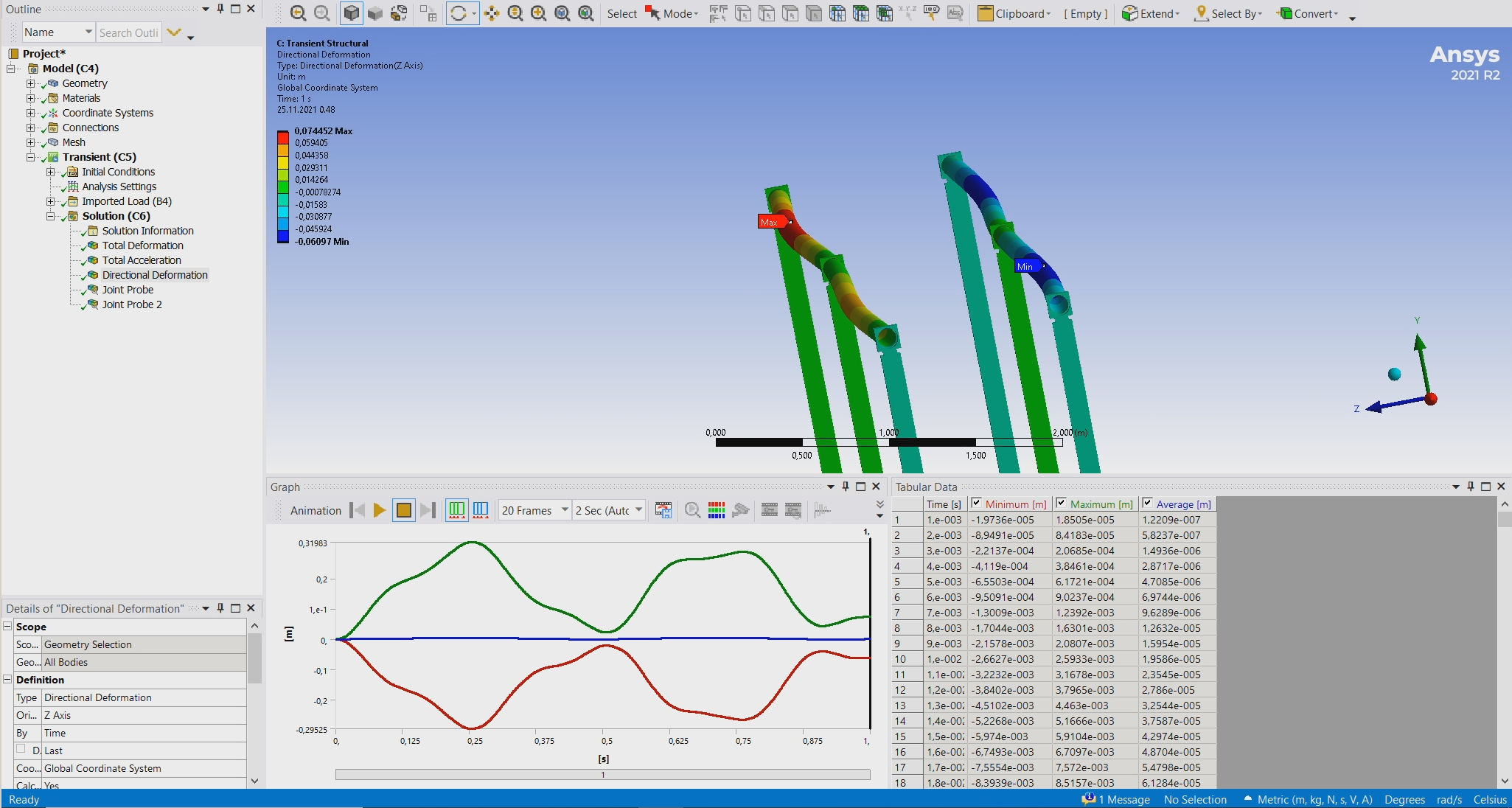
SubscriberTotal Deformation is always positive because it is the distance from the starting point.
Plot Directional Deformation and set it to the Z axis direction. That will show positive and negative values.
November 24, 2021 at 10:52 pmNovember 25, 2021 at 12:41 ampeteroznewman
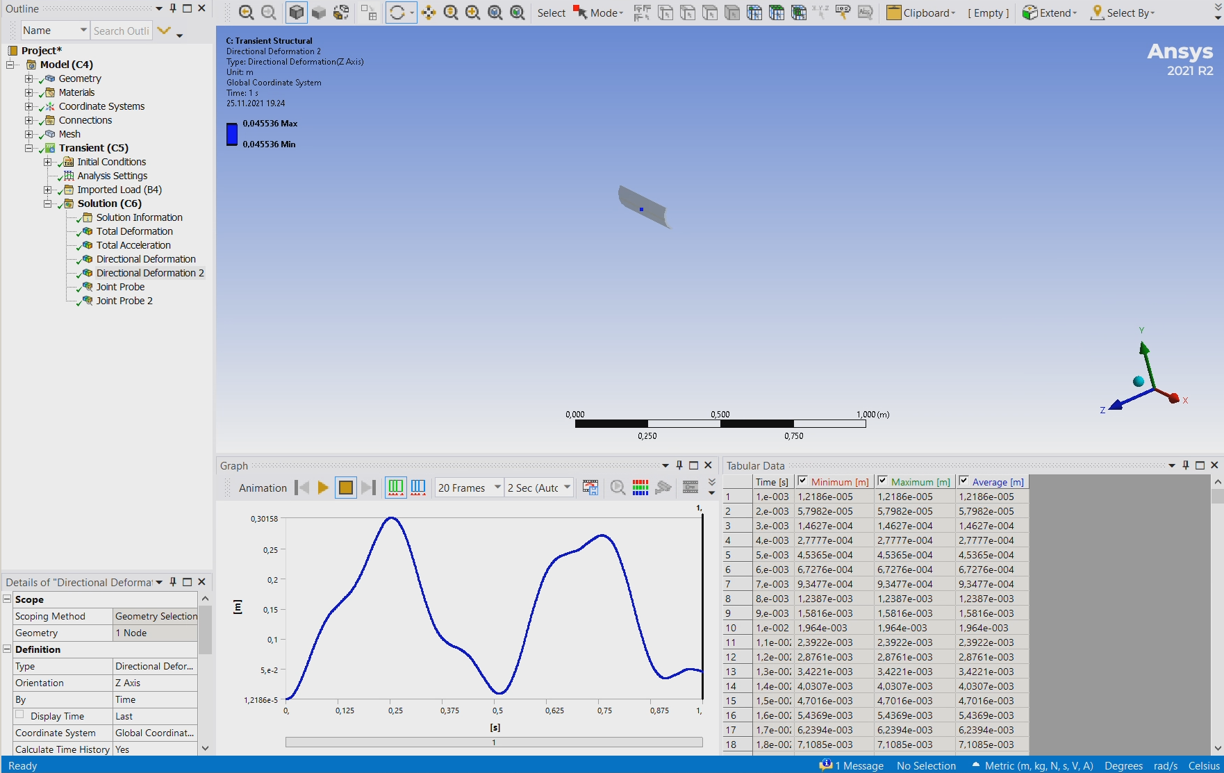
SubscriberSelect a single node at the center of the bar to plot Directional Deformation in Z, that should cross zero.
November 25, 2021 at 5:30 pmNovember 25, 2021 at 6:52 pmpeteroznewman
SubscriberThe deformation shown is the correct simulation result for that model.
If you want a different result, you need to change something in the model.
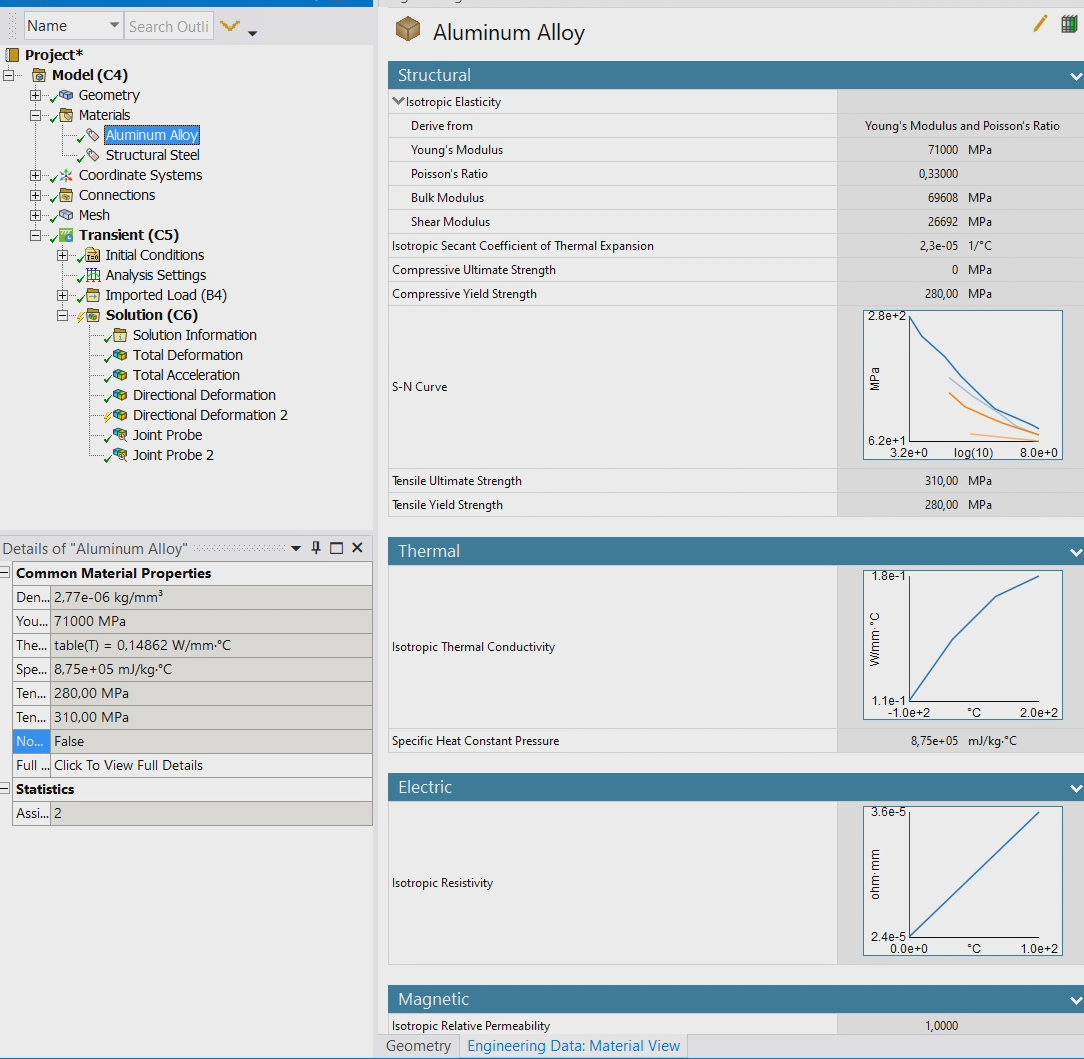
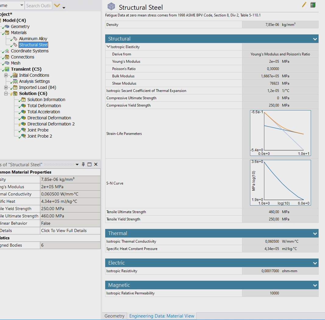
Do the materials include plasticity or are the materials all linear elastic? If you have plasticity, try removing that from the material model.
You could change the imported load.
You could simulate for 1 extra second with no load.
You could change the thickness of the supports.
You could change the thickness of the bus bar.
You could change the density of the bus bar.
I recommend you run a Modal analysis on the structure and learn what the first modal frequency is. I think you have a mismatch between the timing of the Rejecting Force and the natural frequency of the structure.
November 26, 2021 at 6:11 pmNovember 26, 2021 at 6:30 pmpeteroznewman
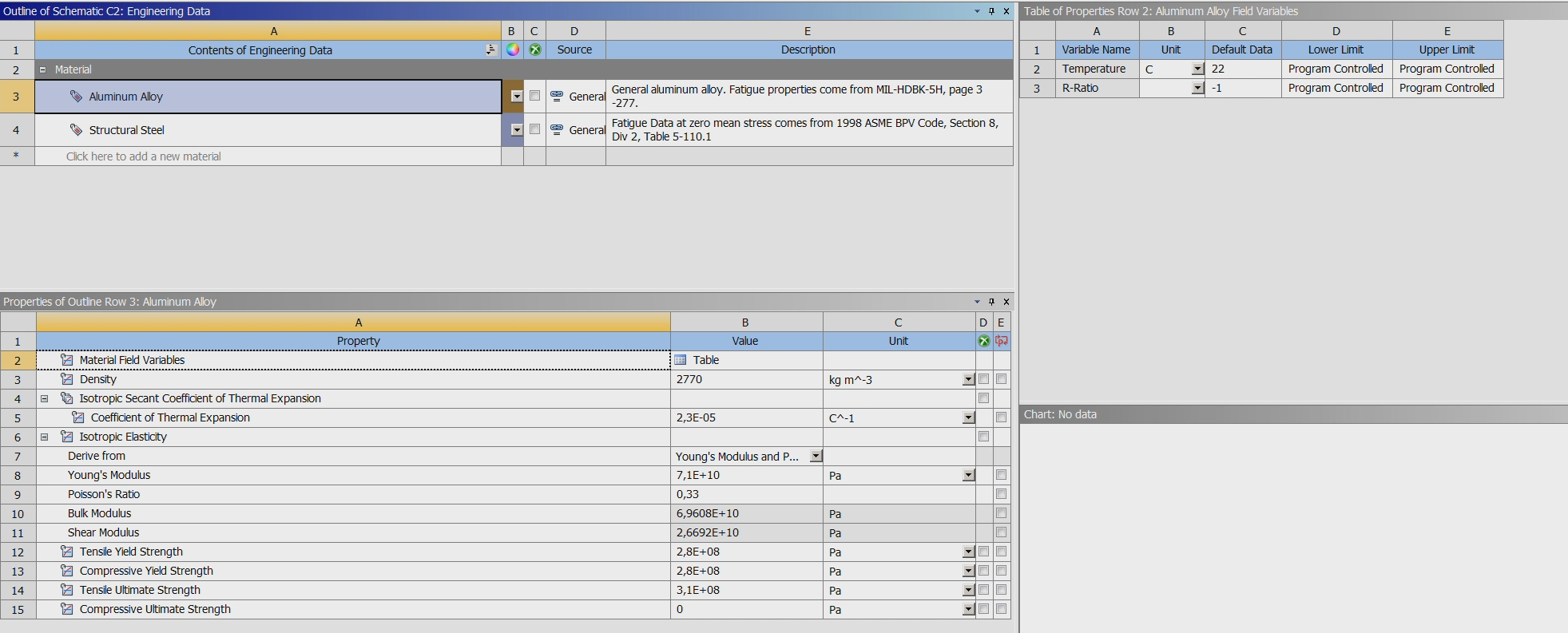
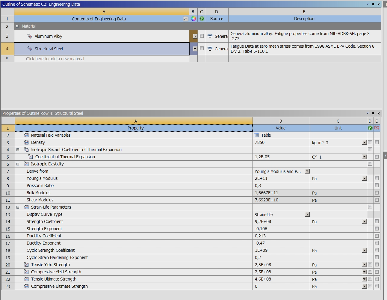
SubscriberThe materials are all linear elastic, so no plasticity.
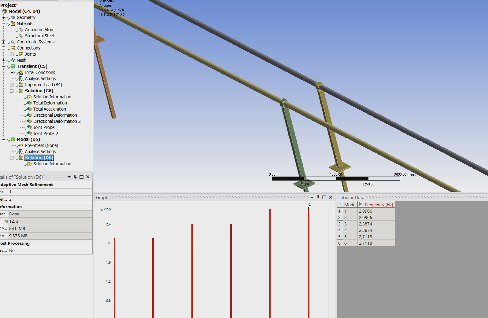
In Workbench, Drag and Drop a Modal Analysis onto the Model cell of the Transient Structural analysis.
Click Solve and reply with the frequency of the first mode. You should compare this frequency with the frequency in the Imported Load.
I can help you calculate the frequency in the imported load. In Mechanical, right click on the Mesh branch then Clear Generated Data. File Save, then File Archive which will create a .wbpz file. Attach that file to your reply and I can open your model.
November 26, 2021 at 7:43 pmNovember 26, 2021 at 8:42 pmpeteroznewman
SubscriberI can't open your archive file because you have Ansys.Ansoft.CoreAddin.Addin and I don't have that installed so it won't let me open the archive.
I'm not sure how to fix that but you can go to Workbench and click on Extension, Manage Extensions...
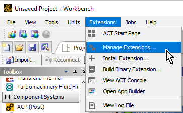 If you see Ansoft in your list, uncheck that and try saving the archive file again.
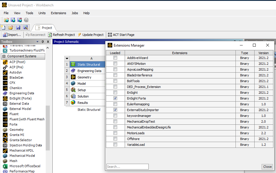 Or you can put the imported load into a spreadsheet and attach that to your reply.
November 26, 2021 at 9:05 pmOROI
SubscriberI did not have Ansoft extension, but only difference was "Speos" extension, so i unchecked that, maybe it now works. Here is also imported load.
November 26, 2021 at 9:48 pmpeteroznewman
SubscriberI get the same error trying to open this archive. I don't know how to fix this problem. I opened my own question to get advice.
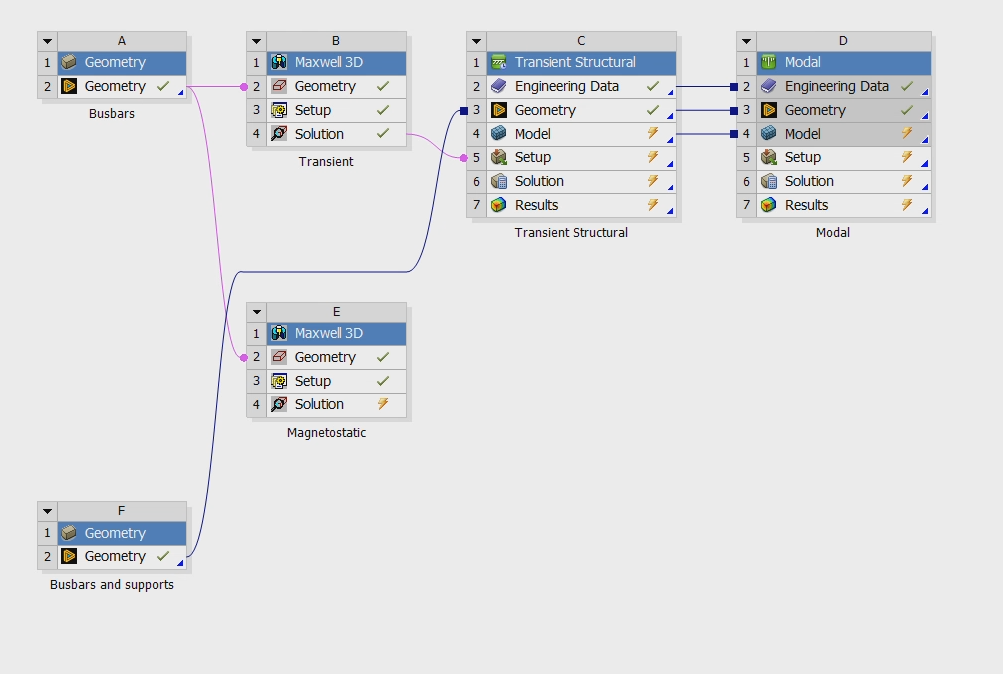
How many other systems are in that project? Is it just a single Transient Structural system? If not, it is the other systems causing the problem. In that case, you can right click on the Transient Structural and just Export that one system.
Unfortunately, the BodyForceDensity file had force components for all elements in the model at a single point in time, not a time history of the load.
Can you plot a time history of the sum of the Z component of forces along the bus bar?
November 27, 2021 at 1:08 amNovember 27, 2021 at 6:00 pmpeteroznewman
SubscriberI was able to open the archive with only the Transient Structural included.
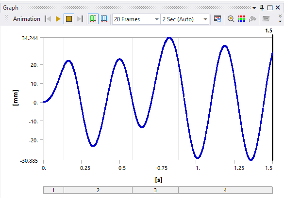
Below are three plots. The first plot is the force on the middle joint that you provided in Probe2.txt. The second plot is a filtered version of that and the third plot is your transient displacement results.
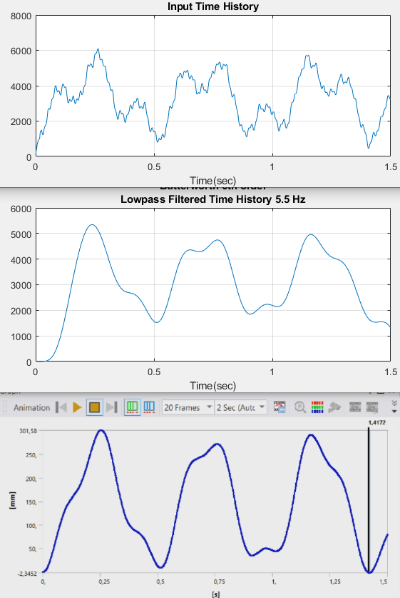 It's clear that the motion of the center of the bar is following the input force, filtered by the mass and stiffness of the structure. Notice that the force is always positive, so it is not surprising that the displacement is always positive.
If you want to see the busbar oscillate back and forth, you need to simulate for 3 seconds, where the first 1.5 seconds has the applied load while the last 1.5 seconds has no load.
November 28, 2021 at 12:33 amNovember 28, 2021 at 4:16 ampeteroznewman
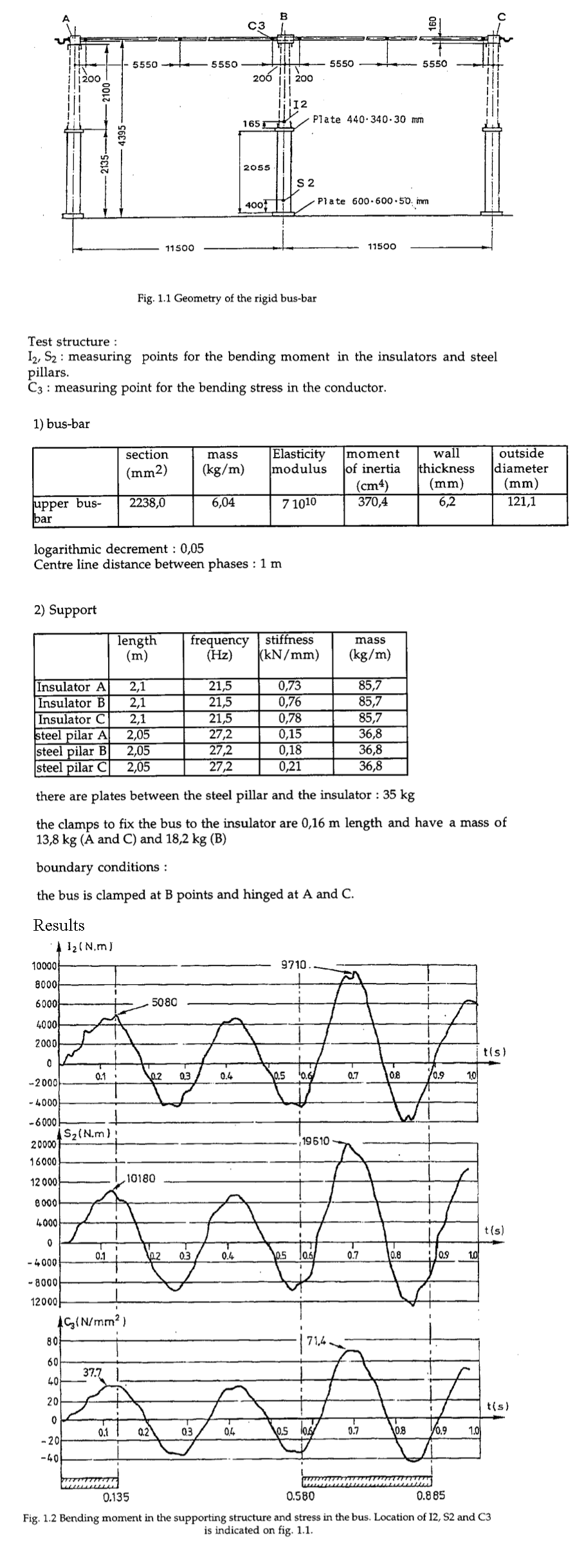
SubscriberAttached is a beam element model of one busbar (the other is suppressed and incomplete). The first mode of this busbar is 2.89 Hz which has a period of 0.346 s. You can see that I have 3 joints. The fixed joint represents the clamp at point B while the two spherical joints represent a hinged connection at points A and C. I adjusted the density of aluminum to get the weight of the busbar correct.
Look at the first cycle on the graphs you show. It has a period of approximately 0.34 s so the model above is a reasonable close representation of the structure.
It seems to me that in this experiment, the power is turned on from t=0 to t=0.135 s then turned off. This pulse kicks the busbar to the side and begins the oscillation. Then from t=0.580 to t=-0.885 s the power is turned on then off to kick the oscillation to a larger positive value and a smaller negative value while the power remains on.
November 28, 2021 at 6:17 pmOROI
SubscriberDecember 2, 2021 at 4:57 pmOROI
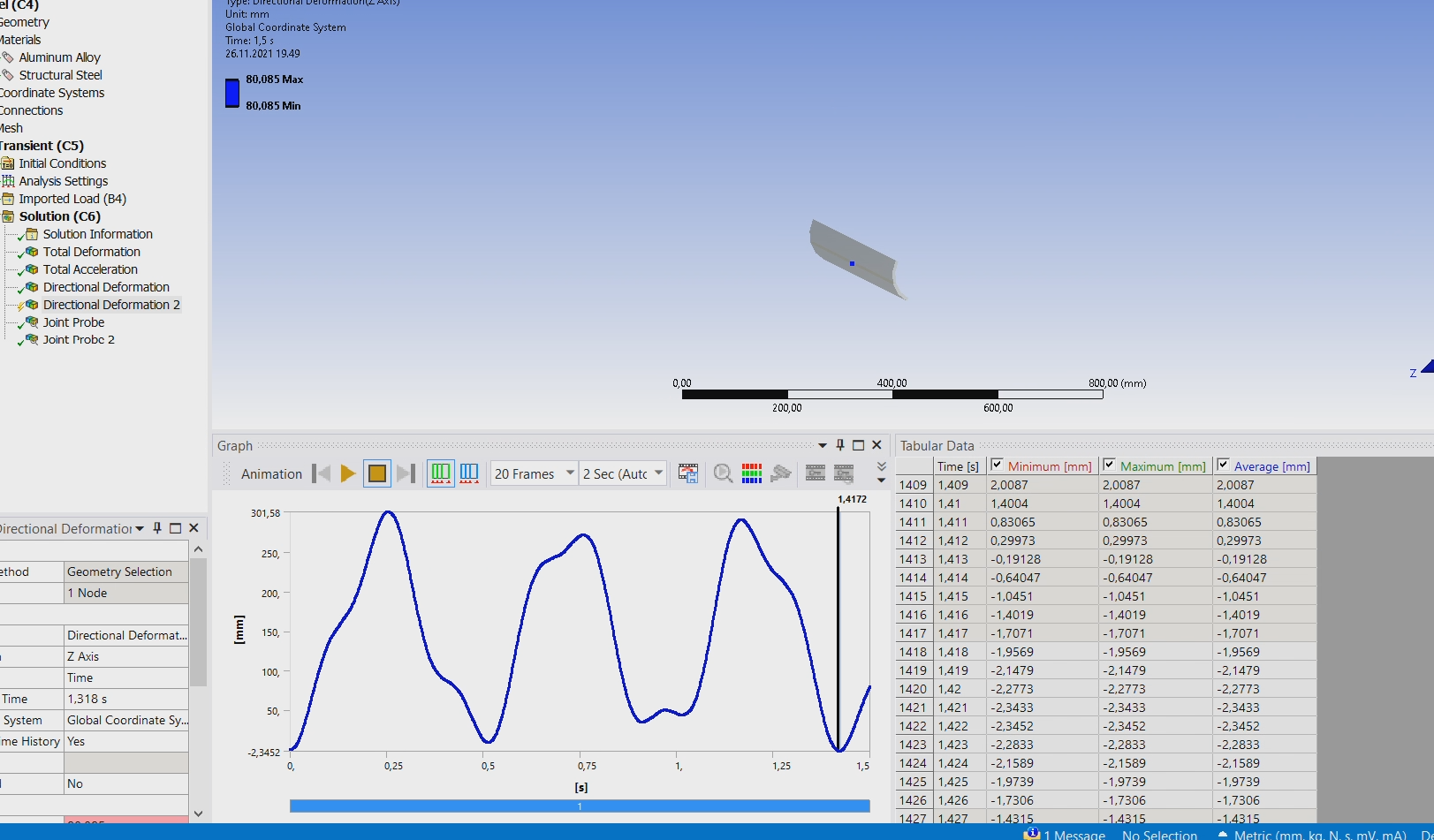
SubscriberI made adjustment for those support pillars and changed end joints from fixed to spherical. Now one cycle time period seems to be close, but still it does not oscillate from positive side to negative like in that report results.
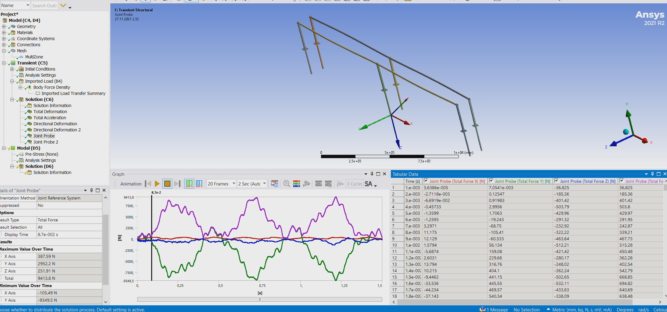
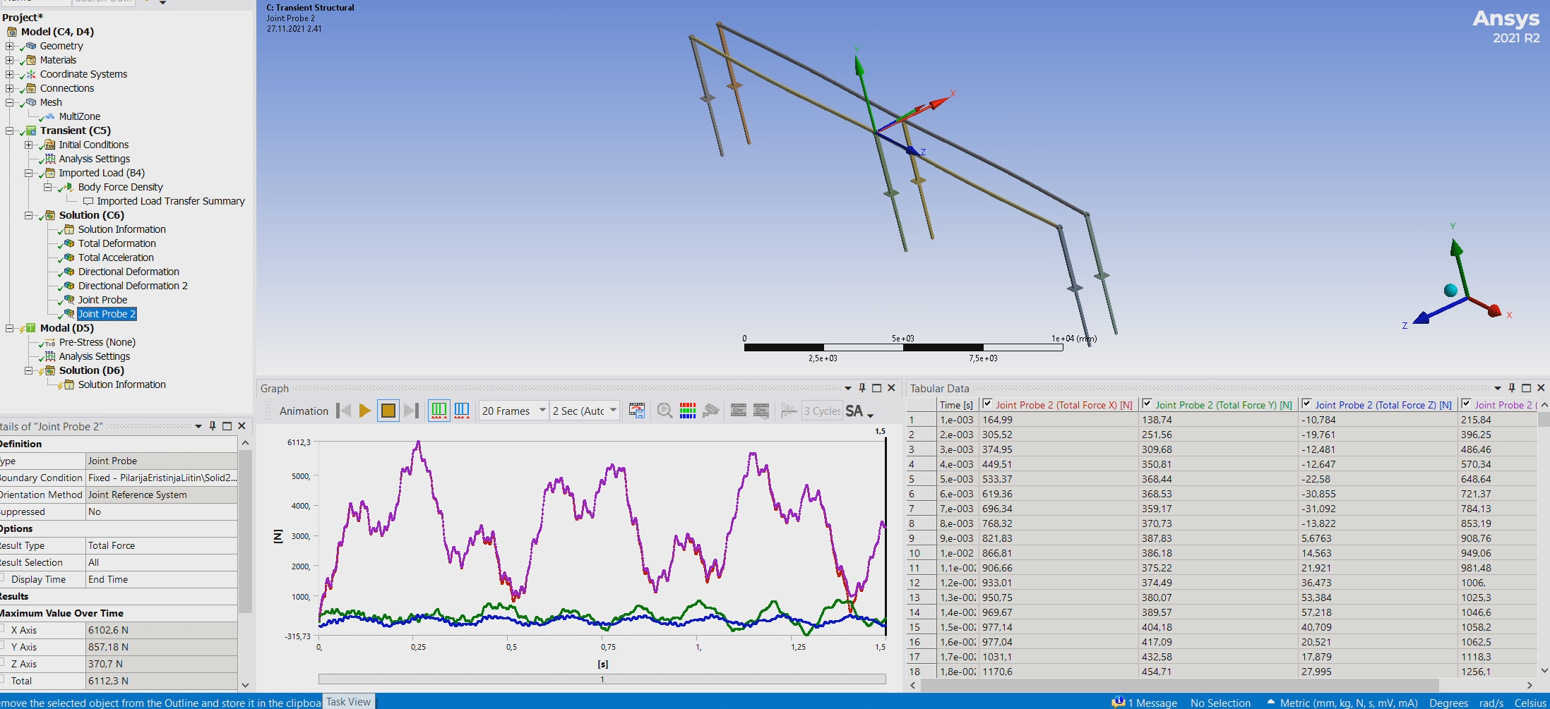
Here is results with high and very low load. It seems to me that the model permanently bends and it gets new zero reference from positive side where it continues oscillation. What i should change to prevent that "bending"happening, if that is the reason for that kind of behavior?
High load, node point middle of busbar.
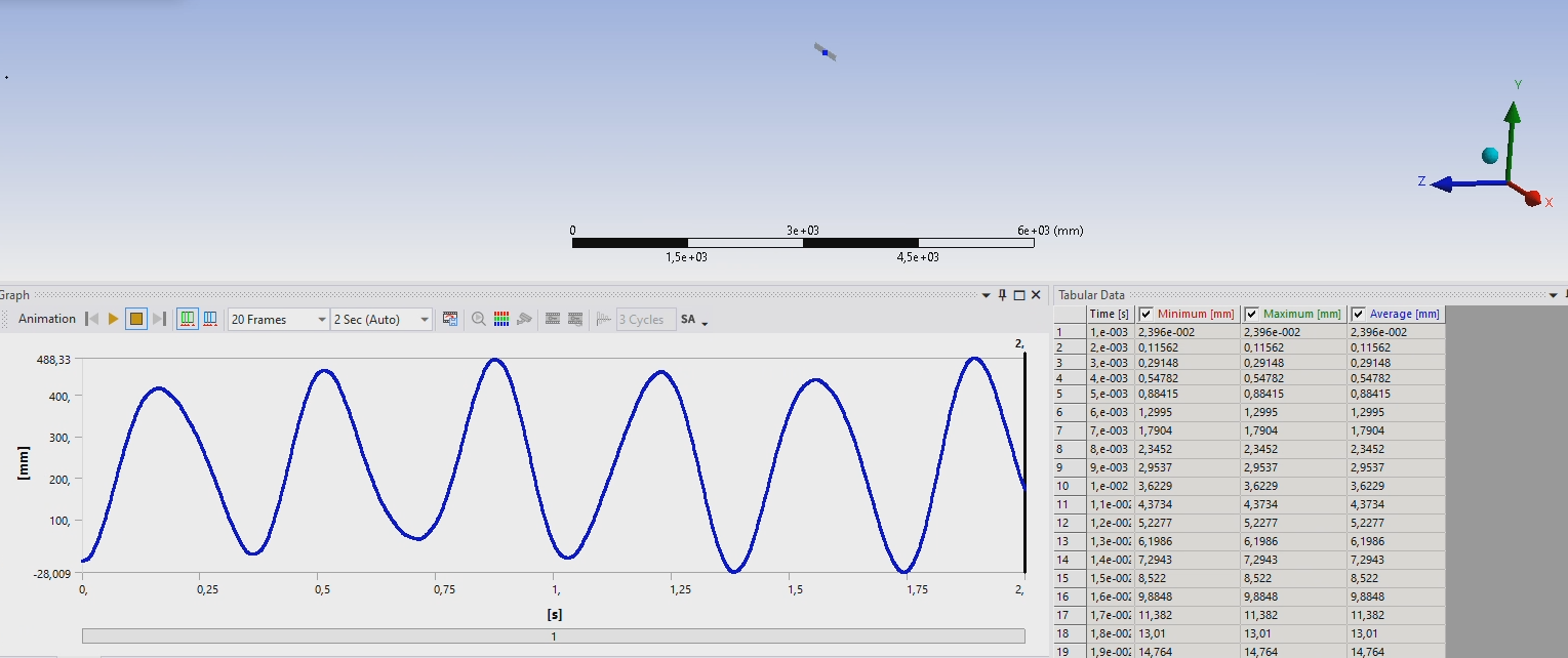
Low load, node point middle of busbar.

December 10, 2021 at 4:53 pmOROI
SubscriberAny thoughts what model parameters i should change?
December 10, 2021 at 10:52 pmpeteroznewman
SubscriberFrom my previous reply...
It seems to me that in this experiment, the power is turned on from t=0 to t=0.135 s then turned off. This pulse kicks the busbar to the side and begins the oscillation. Then from t=0.580 to t=-0.885 s the power is turned on then off to kick the oscillation to a larger positive value and a smaller negative value while the power remains on.
Try this suggestion and see if the busbar crosses zero.
December 10, 2021 at 11:43 pmOROI
SubscriberI have made electromagnetic force timing exactly like in real report result shows, but i got only positive side results. In my mind in this kind of case, mechanical oscillation waveform should usually always go to negative side almost same amount than it was on positive side and fade off gradually to starting point. Could you make similar example model and put some kind of kicking force and see how it behaves?
December 11, 2021 at 2:34 pmpeteroznewman
SubscriberDecember 11, 2021 at 3:24 pmOROI
Subscriberok nice, in Maxwell i can see that the magnetic force turns off, but it seems that there is something wrong in imported load. I have to check that next.
Viewing 22 reply threads- The topic ‘Transient structural analysis: busbar vibration’ is closed to new replies.
Innovation SpaceTrending discussionsTop Contributors-
4783
-
1566
-
1386
-
1242
-
1021
Top Rated Tags© 2026 Copyright ANSYS, Inc. All rights reserved.
Ansys does not support the usage of unauthorized Ansys software. Please visit www.ansys.com to obtain an official distribution.
-
The Ansys Learning Forum is a public forum. You are prohibited from providing (i) information that is confidential to You, your employer, or any third party, (ii) Personal Data or individually identifiable health information, (iii) any information that is U.S. Government Classified, Controlled Unclassified Information, International Traffic in Arms Regulators (ITAR) or Export Administration Regulators (EAR) controlled or otherwise have been determined by the United States Government or by a foreign government to require protection against unauthorized disclosure for reasons of national security, or (iv) topics or information restricted by the People's Republic of China data protection and privacy laws.

