

-
-
August 4, 2021 at 12:55 pm
SalBalazs
SubscriberHello,
I would like to get some additional information about the settings inside Transient DQ machine options.
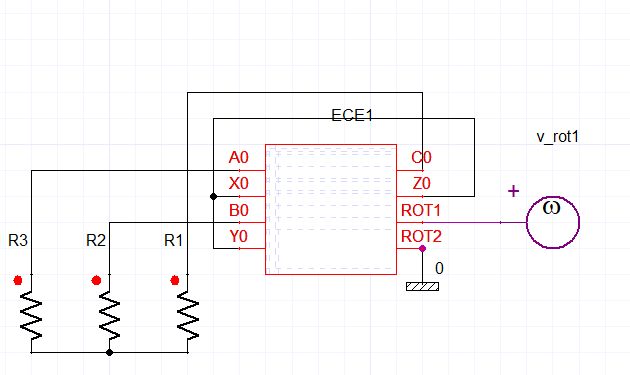
I am simulating a synchrnous machine (claw pole alternator) using ECE3 and ECER models in the external circuit. I have set the DQ current sweeps from -200A to 200A (steps 40A). The simulation is running but I don't know how to setup a transiend DQ report so that I can see the actual DQ currents.
August 5, 2021 at 2:39 pmHDLI
Ansys Employee
The ECE model is to sweep parameters to build .sml file for Simplorer simulation, not a normal transient calculation for an operation point.
It seems to me that we could not use DQ report to create the DQ current for the ECE model. The DQ report should be for the normal transient simulation.
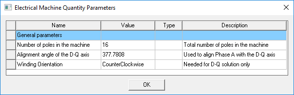
The alignment angle of DQ axis is the angle between D-Q axis and Phase A 's center that based on D or Q alignment in the model and also specified by users.
HDLI
August 8, 2021 at 2:49 pmbordindewdew
SubscriberHello, I want to know which product Ansys simplorer is. Where can I load it?
thanks for the answer
And its can co simulation in ansys maxwell circuit?
August 9, 2021 at 6:02 amSubscriberHello HDLI First of all, thank you for your response, I really appreciate it. ECE model extraction also creates raw data file with .sml file. While I understand your point I would like to differ. DQ currents can be calculated from whatever signal, since it is just math. I am surprised that so far nobody has encountered these issue which I am adressing now:
If you create an RmXprt based model and run an ECE DQ current + position sweep (ECE3 and ECER in maxwell circuit) you can use this Transient Report generator to get the DQ currents.
What this report actually does is that it grabs the phase current and position data and does the Park transformation based on these. The report generator can only deal with data that is already available from the simulation, in this case: Moving1.Position and Current(A)/(B)(C). So whatever data the transient DQ report is providing can only be based on the mentioned natural simulation results.
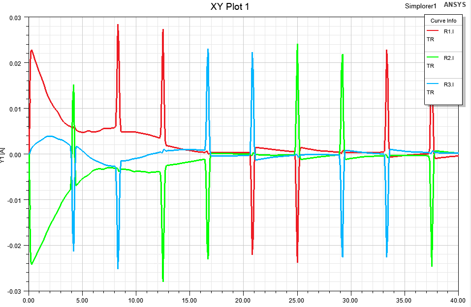
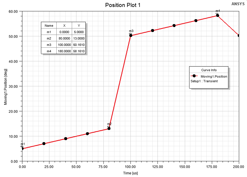
Take my example for instance. I have created a 12 pole machine from rmxprt, the maxwell3D design already includes the Park transformation as output variables. The initial position of the rotor will be 5┬░ (why?). The Park transformation works with this equation to get electrical degrees: (Moving1.Position - 5┬░)*polepairs+180┬░ (why?). Then the ECE simulation starts the rotation, goes up to almost 15┬░mechanical angle and continues the simulation from 50.161┬░ (why?). The above equation for electrical degress should be: (Moving1.Position-5.161┬░)*polepairs+180┬░ because it is not even calculating DQ current liek this properly:
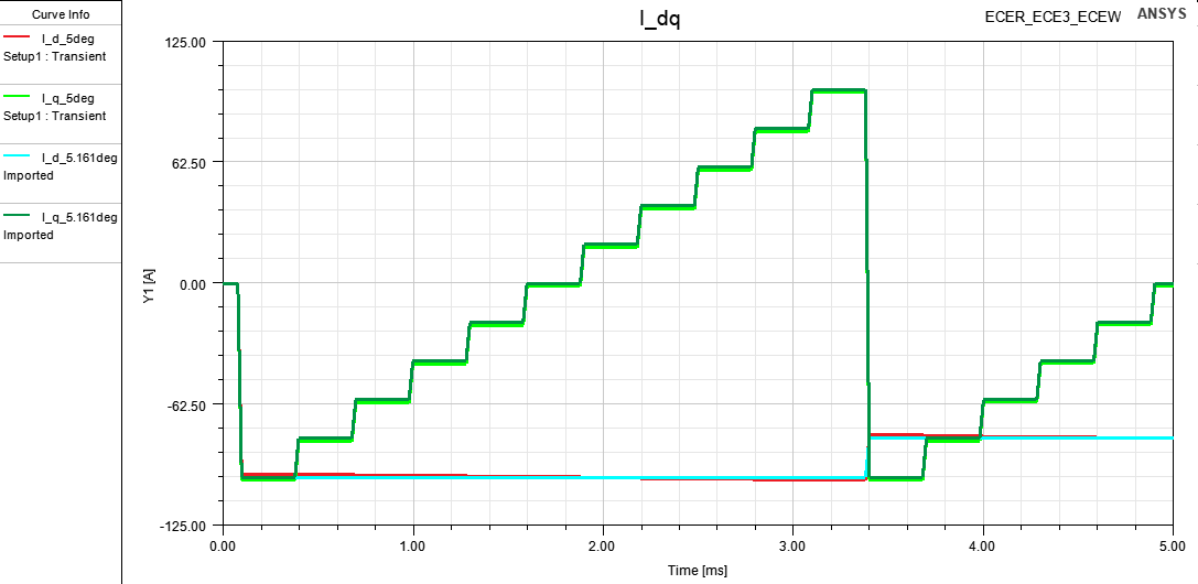 See the small differences? Now see what the transient DQ report creates if I use the alignment angle: 150(why?)-(0.161*polepairs) = 149.034┬░
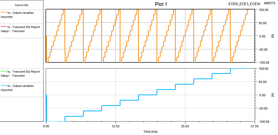 D and Q are mixed but the valeus are exactly the same. I also don't get why it works with this angle.
Now I would really appreciate if an Ansys colleague could explain to me the exact procedure of the calculation, what does winding orientation and alignemnt angel mean exactly? Can anyone give me a link where I can submit bugs?
August 9, 2021 at 6:25 pmAnsys Employee
I find you get a correct dq current by using output variables.
At Id = 0, Iq = 0 and beginning, this process will also perform d-axis alignment calculation with south pole, and run the whole position of RotAngMax angle of ECER component to get the d-axis alignment angle (I called "gamma"), so we will see RotAngMax for the rotating angle of each period.
After that, the ECE model will add the "gamma" and the "initial angle" of motion for the starting angle of the next simulation period. When gamma is 0, it means we have already done the alignment in the model.
Thus, in the second and each simulation period, the angle will start from "gamma + initial angle" to "gamma + initial angle + RotAngMax".
For your example of 12 pole motor, it shows 50.161┬░ for "gamma + initial angle +RotAngMax" and 5┬░ for "initial angle". I suppose you have 15┬░ for RotAngMax, and then the gamma angle is 30.161┬░. It seems to me that the model is with north pole d-axis alignment (30┬░), but also has a slight shift of 0.161┬░ . I suggest to check the stator and rotor geometry to find if the model has the slight shift with the north pole, or increase or decrease RotAngIntervals, and also suggest to try 10┬░ mech. as RotAngMax (360/12/3) and 10 as RotAngIntervals.
BTW, the recommended RotAngMax value is enough to be 60 elec. degreesin many balanced cases for the 3 phase machine. Thanks.
HDLI
August 20, 2021 at 2:39 amdenny9696
Subscriber
I use a synchronous reluctance motor, but it doesnÔÇÖt have a magnet. How to align the d-axis
I used 4 poles 36 slots where the center of phase a is equal to zero on the xy axis
How to adjust the parameters of our ECER ECE3 module to be correct
is_cmd_max=13 A
define q axis at Flux barrier(air gap region)
If ECE3 Current sweep =(1A,3) PhaAngIntervals set 2
ECER RotAngMax =30 RotAngIntervals=60 at 1200rpm time step=0.00025s initial angle=45degree
i got this
 In simplorer my ECE Model IniPos=0 i got a lot of Surge
other question ,what is great setting when i adjust ECE3 ECER parameter ?
 I look forward to your reply. Best regards
August 24, 2021 at 6:23 amSubscriber
Thank you for the explanation, I really appreciate it. In my simulation RotAngMax is 10┬░:
 Math stil does not add up to me. I am using the simpliest possible geometry. I can let go of the fact that I don't know what is happening in the background, since I just want to understand how D axis aligment is meant in Maxwell, and to me it still seems that there is two different approaches. Checking the geometry 50┬░ makes sense, one of the poles is center aligned with PhaseA, OK. The small angle difference may come from mesh resolution or geometrical error, OK. I need to use -30┬░C (+k*90┬░) to get Id Iq currents, I really don't understand where this value comes from.
August 26, 2021 at 4:11 pmAnsys Employee
First, I just find the RotAngMax seems to be 8 ┬░, not 10.
-30 ┬░ is electrical degree, compared to 15┬░ mechanical degree (*2 to electrical degree) in your old setting. 90┬░ might be for transferring d-axis alignment of ECE to angle for q-axis and current, because it is d-axis alignment in ECE model, and in excitation and phase angle, it is angle between current and q-axis. Thanks.
HDLI
Viewing 7 reply threads- The topic ‘Transient DQ Machine options’ is closed to new replies.
Ansys Innovation Space Trending discussions
 Top Contributors
-
peteroznewman
 3597
3597 -
scabo
 1283
1283 -
Dennis Chen
 1117
1117 -
javat33489
 1068
1068 -
Shyam Prasad V Atri
983
Top Rated Tags
© 2025 Copyright ANSYS, Inc. All rights reserved.
Ansys does not support the usage of unauthorized Ansys software. Please visit www.ansys.com to obtain an official distribution.
-


The Ansys Learning Forum is a public forum. You are prohibited from providing (i) information that is confidential to You, your employer, or any third party, (ii) Personal Data or individually identifiable health information, (iii) any information that is U.S. Government Classified, Controlled Unclassified Information, International Traffic in Arms Regulators (ITAR) or Export Administration Regulators (EAR) controlled or otherwise have been determined by the United States Government or by a foreign government to require protection against unauthorized disclosure for reasons of national security, or (iv) topics or information restricted by the People's Republic of China data protection and privacy laws.


