-
-
November 22, 2018 at 7:45 pm
emmanuel_amoako_00
SubscriberHello,
I am working on ANSYS Additive Manufacturing and I am getting the location of the maximum von-mises stress and strain at different places. From the images below, it can be seen that the maximum stress occurs on the build part whiles the maximum strain occurs on the support structure meanwhile stress and strain is directly proportional. Again, since it is using the thermal loads to compute for the structural analysis, I assumed that I will get the same maximum temperature (1400 degree Celsius) used in the transient analysis to do the structural computations. However in this model, the maximum stress (719.48 MPa) occurs at the time of 804.11 s (line 39) with a maximum temperature of 133.72 degree Celsius whiles the maximum strain (0.19037mm/mm) occurs at the time of 421.74 s (line 21) with a maximum temperature of 1400 degree Celsius during the transient thermal analysis. Any suggestions to help solve this issue or an explanation on why I am getting these results will be greatly appreciated.
Regards,
Emmanuel.
-
November 23, 2018 at 5:04 am
Sandeep Medikonda
Ansys EmployeeEmmanuel,
Aren't you looking at just the elastic strain and not the total strain? It is possible that there are plastic strains developed as well. Also, equivalent stress or strain is a cumulative scalar value which doesn't account for the hydrostatic effects.
The temperatures don't have to correspond to the structural response. The structural response will depend on the support it is getting from the surrounding layers and the temperature distribution will additionally depend on the materials thermal conductivity etc. Also, please note that when you look at the AM Process Sequence chart we are typically subjecting both analyses to a different amount of steps.
One thing you can do for better insight is right-click on a solution such as von-mises stress and use Create Results At All Sets to look at layer by layer results.
Regards,
Sandeep -
November 23, 2018 at 5:45 am
emmanuel_amoako_00
Subscriber Hello Sandeep, thank you for your response. Please I am looking at residual stress and strain in the AM process simulation. Please if i understood you clearly, are you suggesting that the different locations might be correct because they are being subjected to different amount of steps.
I wanted to predict that the build part after 3D printing will fail at the location of the max. equivalent (von-mises) stress and strain but since the maximum occur at different places, I wanted to be sure I was getting the right results or there is an error in my results which need to be corrected.
Regards,Â
Emmanuel. -
November 23, 2018 at 5:55 am
emmanuel_amoako_00
SubscriberIt could be seen that the maximum equivalent(von-mises) stress occurs at the 6th layer whiles the maximum equivalent(von-mises) strain occurs at the 4th layer. Are they not supposed to occur at that same layer in the AM build?
-
November 23, 2018 at 6:12 am
Sandeep Medikonda
Ansys EmployeeEmmanuel,
What does the process sequence chart look like in your case? See after the removal of supports there will be additional stresses developing in the material.Â
If you want to make decisions based on the stress, I would recommend you to look at the max. principal stress instead of the von-mises stress?
Regards,
Sandeep -
November 23, 2018 at 6:23 am
emmanuel_amoako_00
SubscriberThank you very much Sandeep, please I will look at the process sequence chart when I get to school. I also appreciate your recommendation of the max. principal stress, I will give it a try and give an update.
Regards,
Emmanuel. -
February 2, 2019 at 7:07 pm
sha88be
SubscriberDear all,
I want to be connected in this case and present my question.
Can this model been save as "additively manufactured model" and after that to have possibility form FEA analysis with different loads?
Â
-
February 2, 2019 at 9:49 pm
Sandeep Medikonda
Ansys EmployeeThe goal of an Additive Manufacturing simulation is to see if the part can be built by understanding the deformations and stresses.
If you already have the geometry and want to subject it to different loads why not just perform a stand-alone analysis? Now, if you want to pre-stress it based on the additive results, theoretically yes, this should be possible using the inistate command but I haven't tried it.
P.S: In the future, please open a new discussion and use the #Permalink to relate to another discussion. Take a moment to review the Guidelines on the Student Community. This discussion has a solution and will be closed soon.
Regards,
Sandeep
-
- The topic ‘
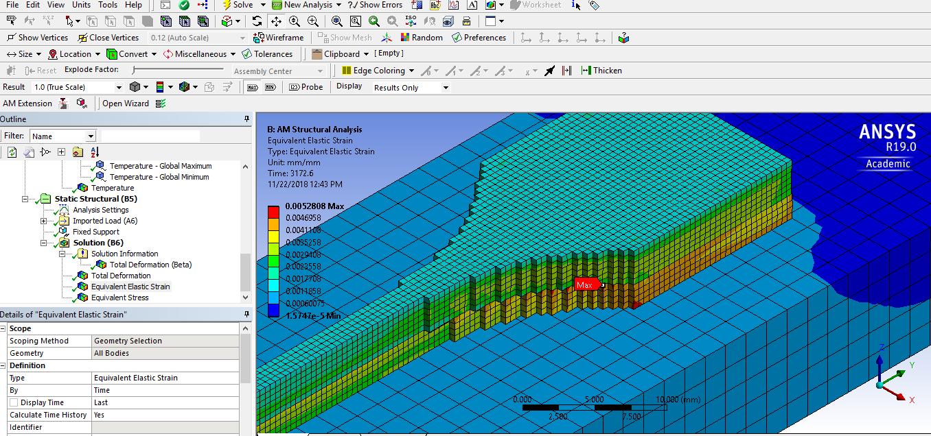
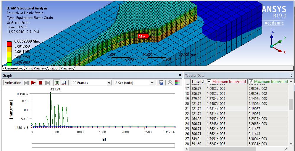
Transient and structural analysis in Ansys Workbench 19.0’ is closed to new replies.
-
2979
-
970
-
857
-
750
-
599
© 2025 Copyright ANSYS, Inc. All rights reserved.