TAGGED: interfacial-cells, laser-heating, solidification-melting, vof
-
-
September 27, 2021 at 6:01 am
Dubey92
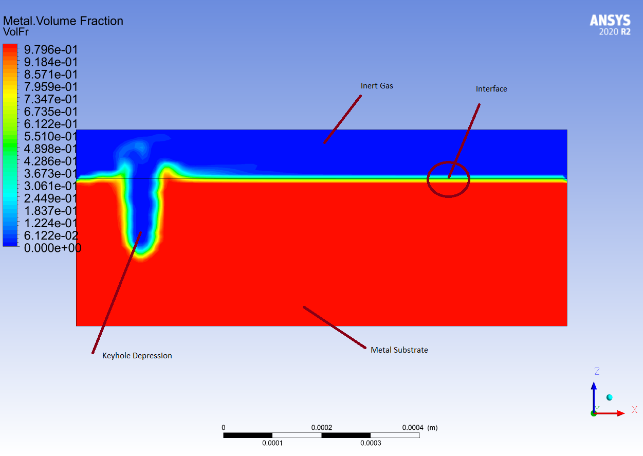
SubscriberI am modeling laser melting of a solid using Solidification/Melting and VOF with an inert gas as the primary phase and the metal as the secondary phase. I want to apply the laser and other heat losses(convection and radiation) at the interface of the gas and the metal. When the laser melts the solid, the surface deforms and the interface location changes continuously. For this, I need to track the interfacial cells continuously at every iteration. The interfacial cells will have a volume fraction of the secondary phase in a given range(say 0.05 to 1) but this value changes in the cells at every iteration due to melting.
I am not an expert in writing UDFs and have started just a few months back. From what I understand, I can get the index of the interfacial cells using F_C0 and F_C1 and update these using DEFINE_ADJUST.
Can someone please give some hints on the correct way of doing this? Any help is much appreciated. Thanks in advance.
September 28, 2021 at 1:58 pmKarthik Remella
AdministratorHello Do you wish to track this information for post-processing purposes? Or do you need to extract this information and pass this along to the solver?
Karthik
September 28, 2021 at 4:01 pmSubscriberThanks for your reply. I want to apply my source terms in these interfacial cells only and the position of interfacial cells will change at every iteration as the laser melts the surface. SO I hope that I should use DEFINE_ADJUST. Next is to get the index of the interfacial cells. For this, maybe I can use F_C0 and F_C1 and store the index in a UDM. I have written a code by taking a help from different online sources. But as I said that I am not an expert so I am not confident that the code is right.
October 25, 2021 at 8:34 amSubscriberI have written a UDF for tracking the interfacial cells at every iteration using DEFINE_ADJUST. The UDF compiles without any error but the simulation crashes and FLUENT closes as soon as I start the calculation. Can you please give some advice about the UDF? I have been stuck with this for a long time now. Here is my UDF:
DEFINE_ADJUST(adjust_interface, domain)
{
Thread *t;
Thread **pt;
cell_t c;
face_t f;
face_t ftop;
cell_t c0;
cell_t c1;
cell_t ca;
cell_t cb;
int phase_domain_index = 1;
real zunit[ND_ND];
real ZDOT;
real es[ND_ND];
real ds;
real A[ND_ND];
real A_by_es;
real dr0[ND_ND];
real dr1[ND_ND];
mp_thread_loop_c(t,domain,pt)
if (FLUID_THREAD_P(t))
{
Thread *ppt = pt[phase_domain_index];
begin_c_loop(c,t)// This will loop over all the cells in the domain
{
real xc[ND_ND];
C_CENTROID(xc,c,t);
NV_D(zunit, = ,0,0,1);
int n;
int top;
C_UDMI(c,t,7) = xc[2];
C_UDMI(c,t,8) = C_VOF(c,ppt);
c_face_loop(c, t, n)// This will loop over all the faces of a cell and n is the local face index number
{
f = C_FACE(c,t,n);
INTERIOR_FACE_GEOMETRY(f,t,A,ds,es,A_by_es,dr0,dr1);
ZDOT = NV_DOT(es,zunit);
ca = F_C1(f,t);
cb = F_C0(f,t);
if(ZDOT == 1 && 0.05 < C_VOF(cb,ppt) < 1 && C_VOF(ca,ppt) == 0)
{
top = n;
}
ftop = C_FACE(c,t,top);// ftop is the global face index number. C_FACE converts local face index number, n to global face index number, ftop
}
c1 = F_C1(ftop,t);// c1 is the index of face's neighbouring C1 cell
c0 = F_C0(ftop,t);// c0 is the index of face's neighbouring C0 cell
/* This is the volume fraction condition */
if (C_VOF(c1,ppt) = 0.0 && 0.05 < C_VOF(c0,ppt) < 1)
{
C_UDMI(c,t,9) = c0;
C_UDMI(c,t,10) = c1;
}
}
end_c_loop(c,t)
}
}
The error is thrown at the line if (FLUID_THREAD_P(t))
November 24, 2021 at 9:54 amSubscriber
November 25, 2021 at 7:11 pmSurya Deb
Ansys EmployeeHello,
You might consider creating a Cell Register with desired Liquid Fraction Range. Then patch a UDM (say value of 1) using this cell register that you created.
You can patch it at a certain frequency using "Execute Commands" .
That way you will have the information of the interface in the UDM and can further use it in other UDFs.
Regards SD
December 15, 2021 at 4:47 pmuser deleted
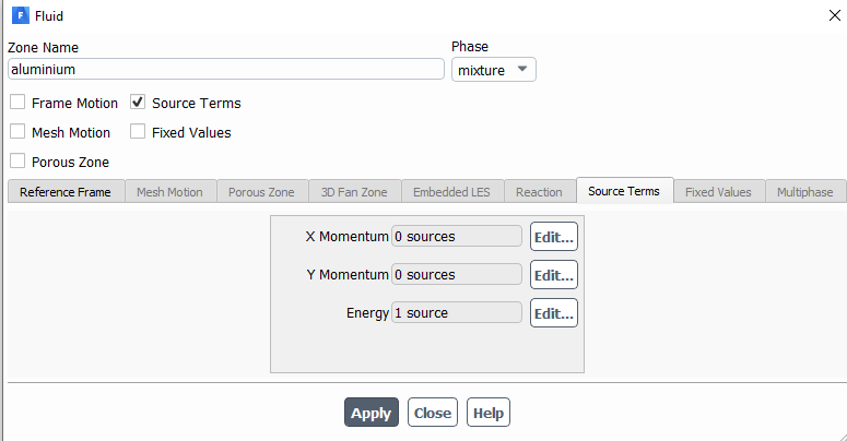
SubscriberHello. Could you please tell me why my DEFINE_SOURCE does not heat the specified area
source = (950 / (3.14 * 0.0015 * 0.0015) * exp (-2 * (r * r) / (0.0015 * 0.0015)));
where r = (x ^ 2 + y ^ 2) ^ 0.5.
This source heats:
vol=2*r*r/(0.0015*0.0015);
volume = C_VOLUME(c,t);
source = (950*exp(-vol)/(volume*0.005))
THANK YOU.
December 16, 2021 at 3:20 pmSubscriberHi! If your problem is single phase, then it should not be much of a problem to apply the source term. Please post your complete code and then others can also see and suggest changes. Mine is a 2 phase flow and applying the source terms is a bit tricky.
December 17, 2021 at 2:01 pmSubscriber
Hi!
Thanks for your reply. This is what I am using.
#include "udf.h"
#include "sg_mphase.h"
#include "mem.h"
#include "sg_mem.h"
#include "math.h"
#include "flow.h"
#include "unsteady.h"
#include "metric.h"
DEFINE_SOURCE(heat_source, c, t, dS, eqn)
{
Thread *pri_th, *sec_th;
real source;
real x[ND_ND],volume,r,k;
volume = C_VOLUME(c,t);
C_CENTROID(x, c, t);// Acquire the cell centroid location
real T = C_T(c,t);
pri_th = THREAD_SUB_THREAD(t, 0);
sec_th = THREAD_SUB_THREAD(t, 1);
r=sqrt(pow(x[0],2.0)+pow(x[1]-0.002,2.0));
k=(pow((3.46/0.003),2.0)); // concentration factor
if(C_VOF(c,sec_th)>0.55 && C_VOF(c,sec_th)<1)
{
if (r<=0.0015)
{
source = (950*exp(-k*r*r));
dS[eqn] = 0.0;
}
else
{
source = 0.0;
dS[eqn] = 0.0;
}
}
else
{
source = 0.0;
dS[eqn] = 0.0;
}
return source;
}
Such a source does not generate heat.
2 Phase Mode is in use.
I also found that, before the material melts, X, Y momentum act on heating, even if they do not heat up to zero.
If you turn off X, Y momentum, turn off heating appears, but still this is not enough.
The question is, what am I doing wrong? I've spent a lot of time looking into this problem. Heating can be obtained if instead of 950 there will be about 1e10
December 20, 2021 at 5:34 pmSubscriberI assume it's a steady state problem as there is no time involved in your heat source and you are using VOF for multiphase. Can you tell what are your two phases? Also, please explain in detail your problem statement as that is the basic requirement for anyone else to be able to provide any help. You can see my earlier posts on how to define the problem completely such as what is your purpose? what models you are using? etc.
Viewing 9 reply threads- The topic ‘Tracking interfacial cells in 2 phase VOF’ is closed to new replies.
Innovation Space Trending discussions
 Top Contributors
-
peteroznewman
 5009
5009 -
scabo
 1681
1681 -
Dennis Chen
 1387
1387 -
javat33489
 1248
1248 -
Shyam Prasad V Atri
1021
Top Rated Tags
© 2026 Copyright ANSYS, Inc. All rights reserved.
Ansys does not support the usage of unauthorized Ansys software. Please visit www.ansys.com to obtain an official distribution.
-