TAGGED: calculation, torsional-stiffness
-
-
April 3, 2025 at 12:40 pm
tristan.lacombe
SubscriberHello,
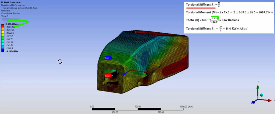
On the video "Post Processing & Parameterization of FSAE Composite & Monocoque Chassis Analysis in ANSYS - Part 6" from Ansys How To on Youtube, the torsional stifness is calculated with the maximum displacement as follow
My question is why the maximum value is taken and not the absolute maximum value which should be 3.19mm?
Thank you,
Tristan
-
April 4, 2025 at 12:33 pm
Akshay Singh
Ansys EmployeeHello Tristan,If the analysis is focused on a specific section(critical section) or component of the structure, the maximum deformation in that specific area (0.33 mm) would be more relevant than the absolute maximum deformation in the entire model. The value is used for calculating theta (s = r * theta).The value 0.33 mm represent a deformation that is directly related to the torsional behavior being analyzed. This could be a critical deformation that affects the torsional stiffness calculation. The absolute maximum value of 3.19 mm might be a result of other factors or boundary conditions that are not directly relevant to the torsional analysis being performed.This is a tutorial problem, for actual chassis, please refer to the guidelines provided by governing committee(FSAE) for calculations.
-
Viewing 1 reply thread
- You must be logged in to reply to this topic.
Ansys Innovation Space


Trending discussions


- Calculation of Contact Normal and Traction Forces
- Car projection lamp Zemax design
- Torsional Stiffness calculation
- Interested in ROM building and deployment course
- Unable to login to Ansys Learning Hub
- FSI calculate OSI
- An internal solution magnitude limit was exceeded
- Correction in a file
- Foundations in Stress Analysis. Question about deviatoric and volumetric strain
- Cant find a resource file of Fluent tutorial guide
Top Contributors


-
3150
-
1013
-
956
-
858
-
797
Top Rated Tags


© 2025 Copyright ANSYS, Inc. All rights reserved.
Ansys does not support the usage of unauthorized Ansys software. Please visit www.ansys.com to obtain an official distribution.


