-
-
February 8, 2024 at 2:38 pm
akndnzmn
SubscriberHello,
I have a circular shaft and I want to find out at what torque the shaft will break. I don't know how to set up the analysis to get accurate results. First thing that comes to my mind is solving the analysis in the transient module with gradually increasing the applied torque force at each time step until large deformation occurs, but instead of transient approach, should I approach the analysis by examining the stresses on the shaft at different torques in the static module? What type of setup should I use or do I need different setup to find critical torque?
Also to find required torque, what material properties do I need to assign?
I have added a similar system below that I will use in the analysis. Shaft is bonded on one side, torque is applied on the other side. Can someone help me about this analysis?
-
February 9, 2024 at 2:08 pm
peteroznewman
SubscriberUse Static Structural, not Transient.
What material is the tube made from? Is it a brittle material such as glass? You can break glass when the stress exceeds the ultimate tensile strength. If it is a ductile material such as aluminum, the material will flow instead of break when the stress exceeds the yield strength. Instead of using the word break, you might use the word fail. Just because some amount of a metal tube material exceeded the yield strength doesn’t necessarily mean it has failed. It depends on what the tube is used for.
You need to know the material properties for the material to do this analysis, at a minimum the Young’s Modulus, Poisson’s Ratio and Yield Strength.
-
February 12, 2024 at 10:27 am
akndnzmn
SubscriberHi Peter,
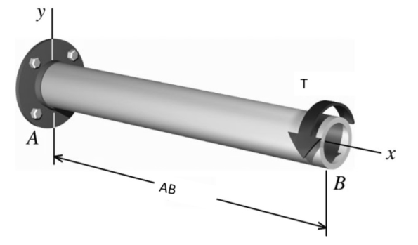
The material is made of 51CrV4 and is quenched and tempered. Also tube is part of a steering systems. I found the material properties and performed the analysis with large deflection in static structural. Thank you for your help. I have a small question about interpreting the results.
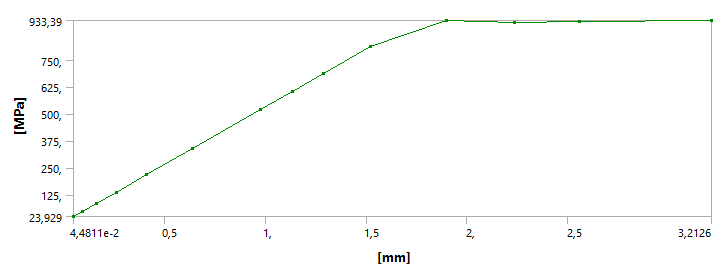
The maximum yield strength of the material is around 900MPa. When I apply a 45 Nm moment while doing the analysis, the system converges and the maximum stress is found to be like 920 MPa. When I increase the applied moment above 45 Nm, the analysis does not converge and gives an error after a point. In an article, it was said that one of the reasons why the analysis in Static Structural does not converge may be due to the forces not being able to balance each other. Also It was mentioning that if a large deformation occurs in the part, this deformation cannot be seen in the static structural, and therefore the analysis does not converge. So, while interpreting the results at which the system fails, can I say that the system is critical and may fail at points where the moment exceeds 45 Nm because system does not converge after that moment?
Also Is there any relation between deformation-stress graph and stress-strain diagram? I mean when I look at the deformation-stress graph below, can I say that the system is in the plastic region after the point where there is a sudden change in the line?
-
-
February 12, 2024 at 10:53 pm
peteroznewman
Subscriber"In an article... it was mentioning that if a large deformation occurs in the part, this deformation cannot be seen in the static structural..." What article? This statement is false.
Did you add a Plasticity material model in Engineering Data? Please show a screen snapshot. It seems like you may have done so because the stress plot flattens out.
You can plot a result called Equivalent Plastic Strain. That will show you where the material has gone past the yield point. Look at the tablular data and some of the early time steps have a 0 value. These are the times when the stress is below the yield strength. You can correlate the last time step with a 0 plastic strain to the applied Torque and say that is the highest torque before the onset of yielding.
-
- The topic ‘Torsion Analysis of Circular Shaft Set-up’ is closed to new replies.
- At least one body has been found to have only 1 element in at least 2 directions
- Script Error Code:800a000d
- Element has excessive thickness change, distortion, is turning inside out
- Elastic limit load, Elastic-plastic limit load
- Image to file in Mechanical is bugged and does not show text
- Help to do quasistatic analysis in static structural module
-
1932
-
823
-
599
-
591
-
366
© 2025 Copyright ANSYS, Inc. All rights reserved.