Hello Huiliu.n
1°/ Concerning the mesh, here are the settings I have chosen:n_ General setting:n

_ Method:n
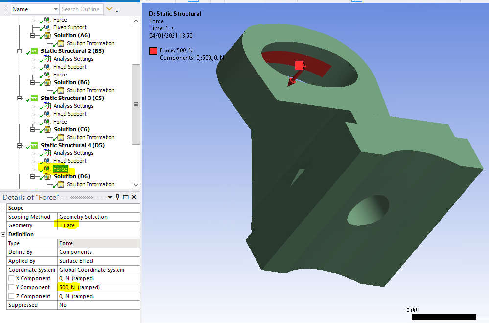
 2°/Concerning the boundary condition and loading, here the definition apply:
n_ the fixing hole being the fixed point (Valid for all 4 loads):n

_ An inner side of the hanging ring. One side per direction and per load value:nLoad according to F3= 500Nn
Load according to -F2 = 6000Nn

nLoad according to F2 = 6000Nn

nLoad according to F1= 1000Nn

n
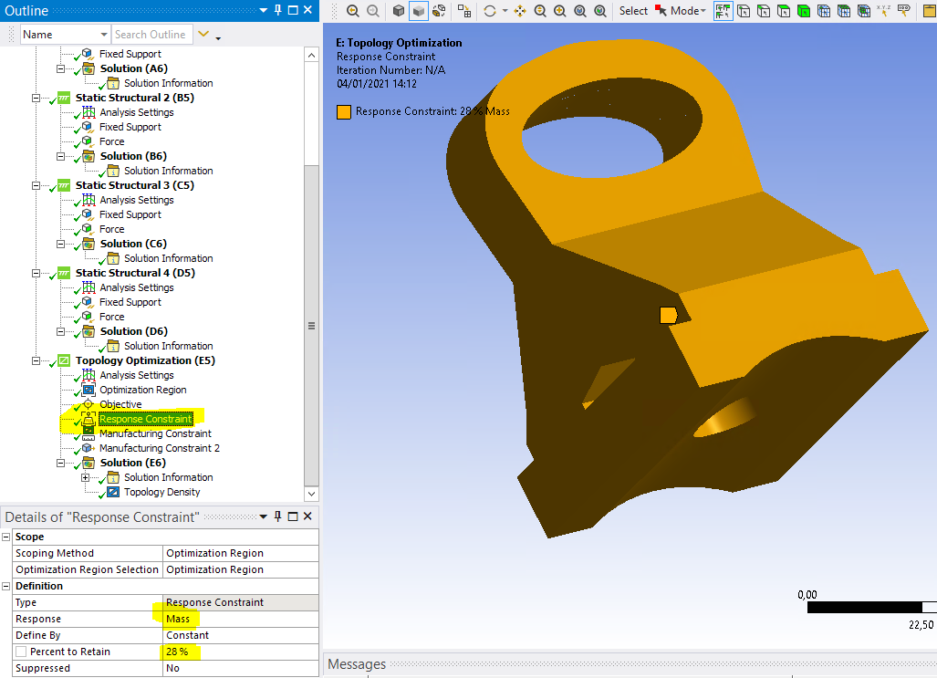
3°/And concerning the topology optimization, here the definition apply:n_ Analysis settings : default valuesn_ Optimization region:n

n_ Objective: Compliancen

_ Response constraint: Massn
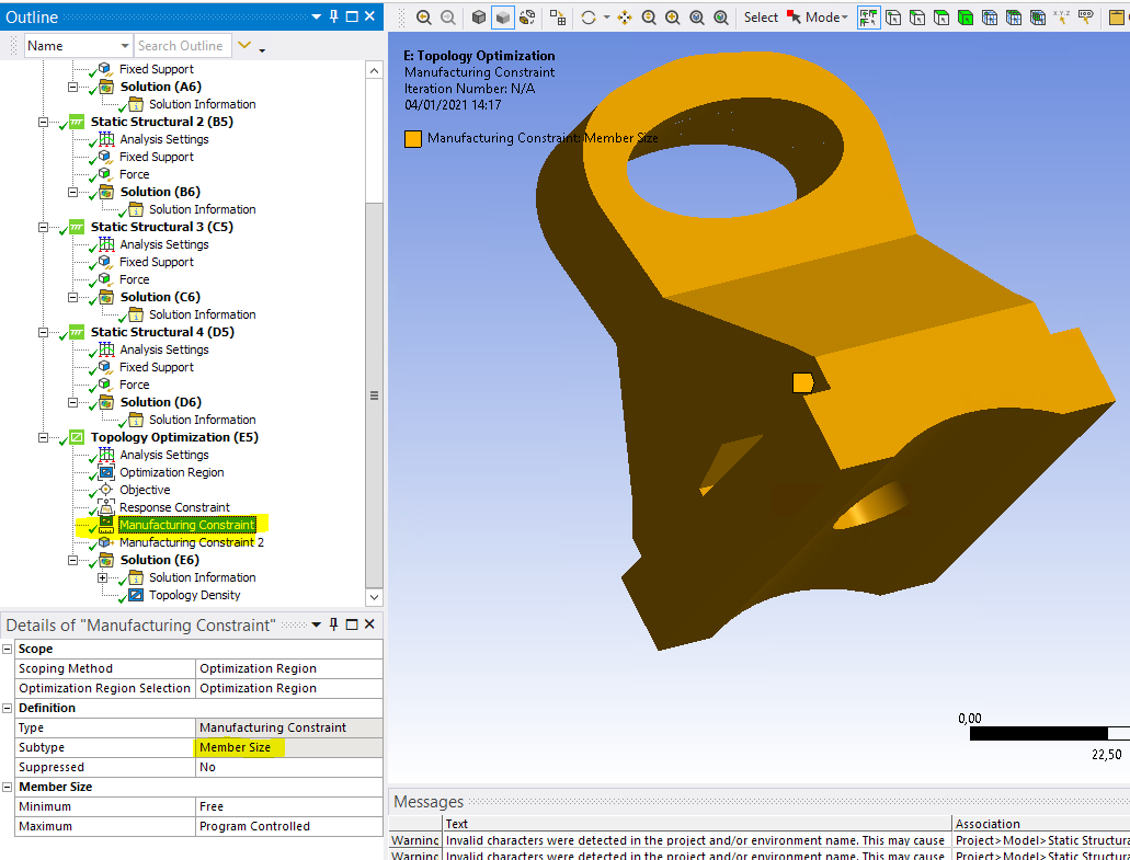
_ Manufacture constraint: Member sizen
_ Manufacture constraint: Pull Out Directionn
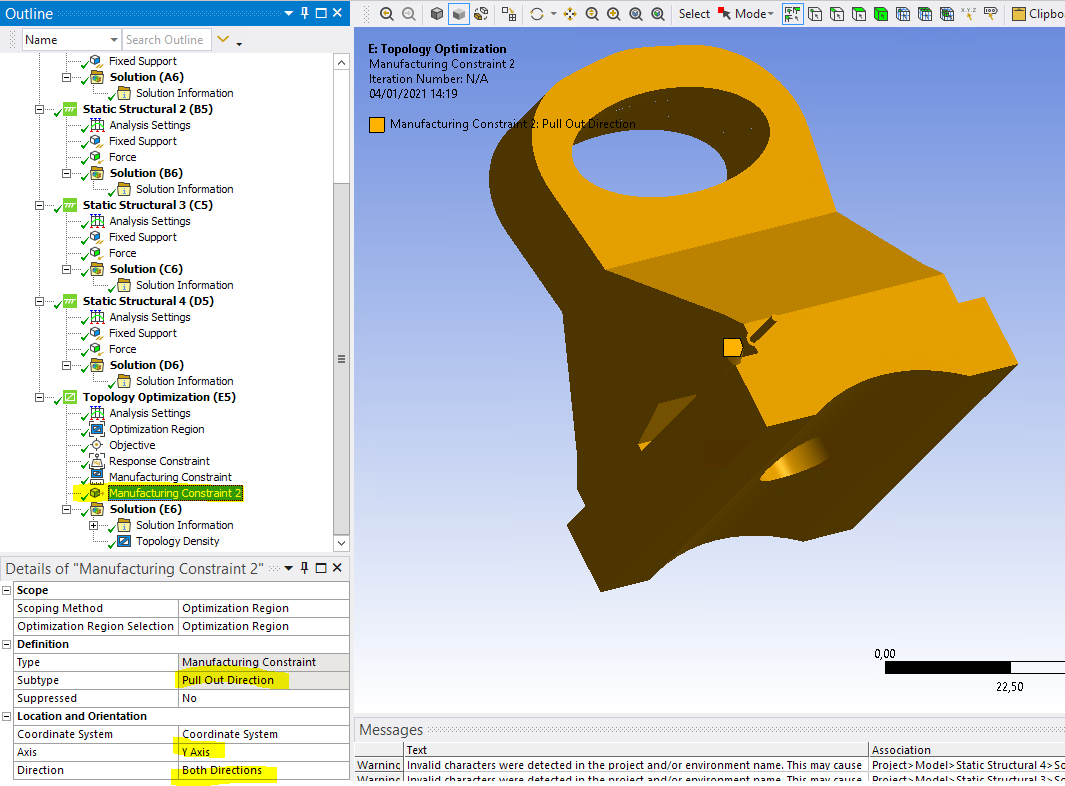
nIs that you see in these settings an explanation for the imbalance in the result of the topology optimization. nThanks in advance for your help.nBest regards?nPhilippe.n


 nCould my problem come from the F3 effort which is not symmetrical (just oriented in one direction)?.


