-
-
May 22, 2023 at 11:37 am
Noam Badt
SubscriberDear ansys team .
TLDR: why does topological optimization use the spatial interpolation of "specified position", instead of "nearest mesh cell", it creates errors.
Long:
I am learning how to use the topological optimization in lumopt + FDTD. when working on my project, I stumbled upon FDTD mesh grid vs optimised geomtry error, which I also found how to recreate using the following example.
following the 2d example in y splitter topology example link the example runs ok as-is.
However, when changing line 26 in file "splitter_base_2D_TE_topology.lsf" to
set('x max',-opt_size_x/2 - 0.5e-7);
which means making the input waveguide to be outside of the optimization area, I get this error:
File "C:\Program Files\Lumerical\v231\api\python\lumopt\geometries\topology.py", line 158, in check_param_count_matches_bounds
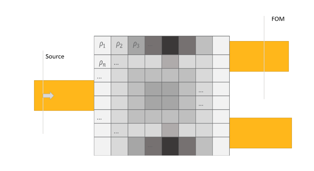
UserWarning: Project file structure 'initial_guess' reports 13832 parameters where expected 13741. This can occur when the number of x, y coordinates specificed to LumOpt do not match the dimensions of the FDTD grid. Try using similar or divisible delta values (size of a pixel) across all the axes.
Note that the amount of displacment is important, -0.5e-7 will cause the error, whereas -1e-7 wont.
Also note, I didnt change the optimization area, the FDTD size, the mesh grid setting or anything relevant. just the WG
my debugging:
after adding a breakpoint in topology.py, line 185
I noticed that indeed the "opt_fields" x resolution is of 152, whereas the x_geo resolution is of 151.
I think that somehow changing the wg position changes the mesh.
possible fix I found:
change lines 366-367 in topology.py to:set_spatial_interp(sim.fdtd, 'opt_fields', 'nearest mesh cell')
set_spatial_interp(sim.fdtd, 'opt_fields_index', 'nearest mesh cell').
Then optimization runs OK.My question: why does the spatial interpolation of opt_fields & opt_fields_index set to "specifed postion"? The goal should be to force that three data positions are identical:
- opt_fields (for gradient calcualtion)
- opt_fields_index (for reading the eps )
- import object(through which the epsilon is changed)
Then why not force all three to "snap" to the same grid? is it because I cant set the import object to snap to the FDTD mesh?
Thanks, Noam -
May 29, 2023 at 9:55 pm
Taylor Robertson
Ansys EmployeeHello Noam,
This is a bit tricky, yet common issue in topology. With topology you need to specify the params in python and have those exactly match the FDTD grid. It is often sufficient to ensure that the span and spacing of the opt_region and in python are the same; however, the meshing in FDTD can cause some variation.
The warning you are getting is a comparison of the size of the two objects, and I am not sure exactly why you approach to change the spatial interpolation worked. Since the check simply compares the sizes it may be that there is some discrepancy in the coordinates that FDTD (opt_fields, opt_fields_index ) and python (import object) are using.
I believe that your assesment is very good, but I am concerned that your interpolation approach isn't the best way to go about fixing it. Bringing the waveguide closer is causing some changes to auto mesh generation.
The reason it cannot simply be defined once, say in FDTD, is because you want to be able to provide initial design through the import object, which uses python's coordinates. So I would avoid the mesh interopolation options because I don't know how this will behave.
A couple things you can do to control the mesh is,
- Use mesh overide if you are not already
- Force symmetric in mesh in FDTD - advanced section
- Use smaller mesh. Auto non-uniform mesh generation does not always use the exact mesh contraints given in mesh override, but if you use a coarse background mesh with refined mesh in opt region it should work.
- If all else fails I simply use a uniform mesh. Easy to set-up, no surprises; although, it probably isn't the fastest or most accurate.
Best Regards,
-
May 30, 2023 at 7:44 am
Noam Badt
SubscriberHello Taylor, thanks for the detailed answer.
Perhaps I should focus on this question:
When reading data from a monitor. with "specified position" set as interpolation.
How does the montitor decide what is the specified position? x min and x max I understand. but how does it choose the resolution? I believe through something that reads the mesh positions... this is the source of the problem. If I could get the monitor to read exatcly where I want, this can be solved without forcing it to read only at the mesh position. (which will also open a path for me to change the topology resoltuion to be different from the mesh resolution, a feature currently missing)
-
- The topic ‘Topology inverse design mesh interpolation’ is closed to new replies.


-
4949
-
1639
-
1386
-
1242
-
1021

© 2026 Copyright ANSYS, Inc. All rights reserved.


