-
-
September 21, 2018 at 8:45 pm
-
September 21, 2018 at 9:16 pm
peteroznewman
SubscriberSam,
It's best to use the Insert Image button and put your image in the post like I show below because the ANSYS employees are not supposed to look at attachments.
My response is that you are showing two beams, not one beam because there is no connection between the left section and the right section.
If you have a structure made with angles where there is a one inch gap between them, presumably at some interval along the length of the beam, the two angles are clamped together on a spacer by some fasteners. You will have to model those connections along the length to model the combination of the two beams to make a beam assembly.
Regards,
Peter
-
September 22, 2018 at 3:16 pm
Sam Fares
SubscriberThank you Peter!
I started to use ANSYS last week.. Below is what i am trying to accomplish. Truss is composed of top chord horizontal member made up of two angles, similarly Bottom chord member, and webs which are diagonal members that are welded to top chord and bottom chord members. Below are more details.
i created the joist or truss profile in Ansys. Not sure how to attach ANSYS model. i just attached Ansys file.
Regards,
Sam
-
September 23, 2018 at 2:32 am
-
September 24, 2018 at 8:18 pm
Sam Fares
SubscriberHi Peter:
Attached is the model.Â
1. Top Horizontal member is continuous member from end to end of Truss. In the model i am using a rectangle to generate the model, but the actual member as i described in my earlier post is a double steel angles
2. Bot Horizontal member is continuous member from end to end of Truss. In the model i am using a rectangle to generate the model, but the actual member as i described in my earlier post is a double steel angles. the size of the angles are different than the Top member
3. Diagonal and vertical members(web) are single members that are sandwiched between the top and bottom horizontal members. Each web end is welded to the top and horizontal members.
4: Piece of wood will be placed on top of Top Member.Lag screws, 5/16" in diameter, will be screwed thru pre-drilled holes in the top member to the wood piece. the screws are 24 inches on center along each angle of top member, but they will be staggered between the two angles. The first holes will be 3 inches from ends of top member. Not Sure how to create and attach this block of wood in Ansys.
5. i used rectangular member to generate the truss in the modeler.
6.I merged the top members together, Bottom members together. i am not sure how to create the connection between the web members and the top and bottom member
Â
Regards,
Sam
Â
-
September 25, 2018 at 2:57 am
peteroznewman
SubscriberHi Sam,
I cleaned up your attached file and applied a 100 kN force at the center to get a 7.7 mm deformation. Here is the Stress in the links.
Attached is the ANSYS 19.2 Archive.
The model you made is like a steel weldment. All the links are welded together.
4) Do you expect the wood to add to the stiffness of the structure? You could leave it out if its main function is to be able to screw things to it. If you need the wood, the simple method which over predicts the stiffness is to use bonded contact between the wood and the steel. The more complicated method is to model the steel angle irons using sheet bodies (not lines), and put the holes in the face where the screws go. Then you put holes in a sheet body that represents the wood. Finally, under the Connections folder, you add Joints of type Fixed to connect each hole in the steel with the corresponding hole in the wood. There is a way to make all the joints automatically with a little bit of prep work.
Regards,
Peter
-
September 25, 2018 at 2:06 pm
Sam Fares
SubscriberI appreciate you and thank you Peter!
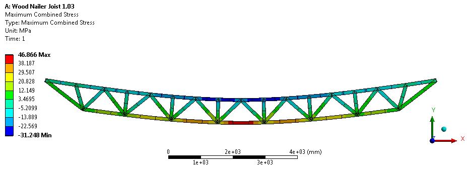
1. what did i do wrong in my model?
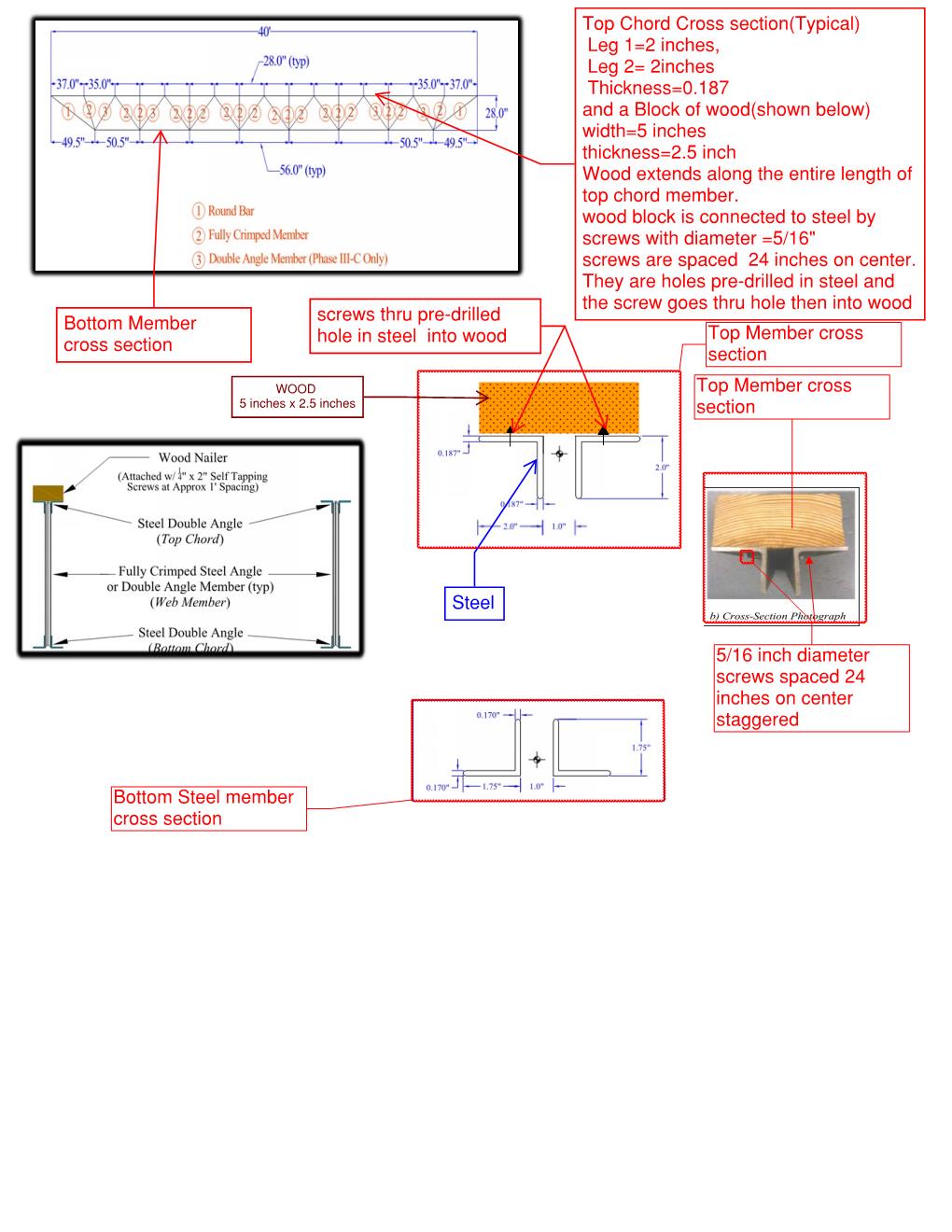
2. To fabricate the truss all the web members will be welded to top and bottom continuous members.
   a.) Did i need to merge the members that make up the top and bottom members ?
   b.) How did you connect or join the web members to top and bottom members?
3. i am investigating the effect of having this block of wood (2.5 inch thick x 5 inch wide) on the stiffness of the joist as well as the load carrying capacity. Screws act as shear connectors and provide partial composite action that will influence the effective depth of truss(joist). i will do also a parametric study on effect of screw size, spacing ,.. on the behavior of joist.
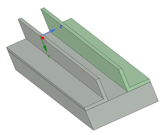
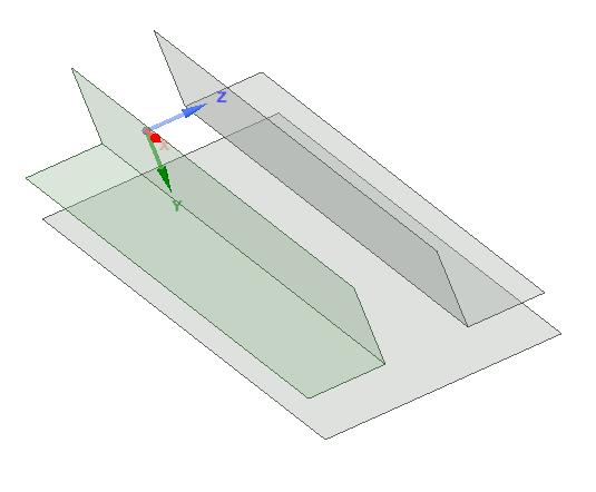
4. How can i generate the double steel angle cross section within Ansys? Is it possible to make the cross section in Autocad and import it and how to import it?
5. i am confused on when do i use "force", "remote force", "displacement" and " remote displacement". i searched for an answer but none is satisfying. Could you explain the difference
6. I am confused on the difference between " shared", "merged", "grouped" topology
Thanks again Peter!
Regards,
Sam
Â
-
September 25, 2018 at 8:49 pm
peteroznewman
SubscriberSam,
1. You can see the supports I applied in the model I attached. A beam has 6 degrees of freedom. Simply supported takes away 3 translations at one end. I added a Displacement and set Y = 0 and Z = 0 to take away 2 more degrees of freedom. That leaves just one, which is rotation about the line connecting the ends of the truss. A Fixed Rotation with just X = 0 is all that is needed to properly support the truss using a pinned/roller type of support. The roller is there because I left X free on one end of the truss.
2. I didn't do anything additional to make the truss be one piece. It was that way when I opened it.
3. Good idea
4. You have to model the double steel angle as two beams. Draw the solid model of the two angles on the wood. Bring those 3 solids into SpaceClaim and create the Midsurface on the Prepare tab. That way you go from solids...
To midsurfaces...
Each surface has the thickness of the solid assigned to the surfaces, and each can have their own materials: wood or steel. If you had holes for screws in these solids, the holes would be in the midsurface also.
5. Use Force and Displacement for now.
6. Use Shared for Shared Topology.
Regards,
Peter
-
- The topic ‘Top Member of Truss composed of two steel angles’ is closed to new replies.
- Unable to attach geometry 2024 R2
- Data Center Simulation
- DXF file loaded incorrectly
- Inventor 2025 files
- Ansys SpaceClaim and Discovery 2024 Facet shelling bug – 2022 version is better
- Spaceclaim 2024 error FNE activation failed
- Simulating PCB
- [SpaceClaim] STEP file size using Converter.exe
- How to do the snap fit insertion FEA?
- Ansys Discovery Crashing vGPU (Reproducible)
-
2042
-
897
-
599
-
591
-
454
© 2025 Copyright ANSYS, Inc. All rights reserved.