General Mechanical

General Mechanical

Topics related to Mechanical Enterprise, Motion, Additive Print and more.

To shell or not to shell, that is the question.

    • lvelasquez
      Subscriber

      Hello,

      I need some guidance related to shell elements formulation. I know that they only have membrane and bending stresses, and it does not have a stress in the normal direction (thickness wise), but what does it means or what implications it has? Just that they have zero stress in that direction (Which I understand that by definition the thickness of a plane is zero) or that they cannot transfer any force in that direction?

      The reason I´m asking is because I´m doing a static analysis for a two-part structure composed of square beams connected by 4 bolts and nuts. I`m meanly interested in contact area of the washer and the beam to see if it will endure the loads and fatigue. The thing is I can´t use solid element for obvious reasons and shell elements.... well, I´m having my doubts after checking the contact pressure result in those elements and it has literally zero. It made me think that the contact is detected but no force is tranfer through it. I have results and the deformation is how I expected to happen, but I´m not sure how condifent should I be.

      Writing this post made me think... Can it be that it has zero contact pressure because it´s in the normal direction but the force is transmited via displacement of the other elements, like the bolt shaft? 

      PD: The forces are applied in the upper structure in those imprints you see in the first picture. The shaft and the washers and solids, everything else is shell.


    • Kaushal Vadnere
      Ansys Employee


      Hi

      Shell elements generally do not have stress component in thickness direction. That means you cannot get stress distribution through the shell thickness so, top and bottom faces of the shell will have same stresses.
      But they do transfer force in out of plane direction as bending stress component exist. The reason you might be getting zero contact pressure on shell elements is because the default contact behaviour is ‘Asymmetric’ and using this behaviour, results are only reported on the contact side (I am assuming you have selected the solid body as contact and shell body as target). You can check in the Initial Information in Contact tool that only contact side is active for assymetric contacts. If my assumption is right, try changing the contact behaviour to ‘Symmetric’ and solve again to check if you get contact pressures on shell body as well. Also, I believe you have scoped multiple contacting pairs in single contact object, this is not recommended. Plase create different Contacts for every individual contact pair and make sure that you have set Shell Thickness Effect to Yes and select appropriate Contact Shell Face in the details of contact.
      To learn more about contact formulations and behaviours, please refer to this article in Ansys Help Document: 9.6.3.2. Definition Settings
      If you cannot open the above link, refer this: How to access the ANSYS Online Help
      Refer to these free Ansys Innovation Course on Contacts: Contact Mechanics | Ansys Innovation Courses, Fundamental Topics in Contact | Ansys Innovation Courses
      You can refer to Lesson 2 of this free Ansys Innovation Course to learn more about shell modeling: Geometry Representation | Ansys Innovation Courses
      Hope this helps. 


    • lvelasquez
      Subscriber

      Hello Kaushal,

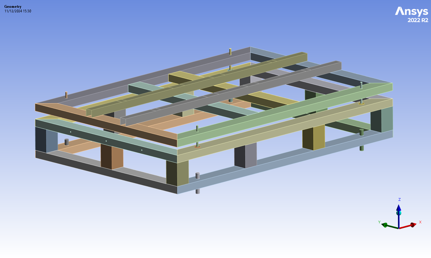
      Ok, so it´s just that I can´t check stresses inside the elements. Got it. But just to be clear, the use of midsurface is valid? Like I´m not considerly over simplying the model and hence getting lower stress/strain results?

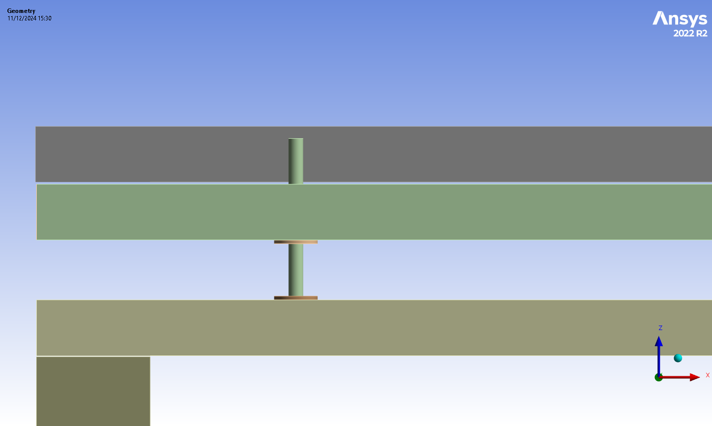
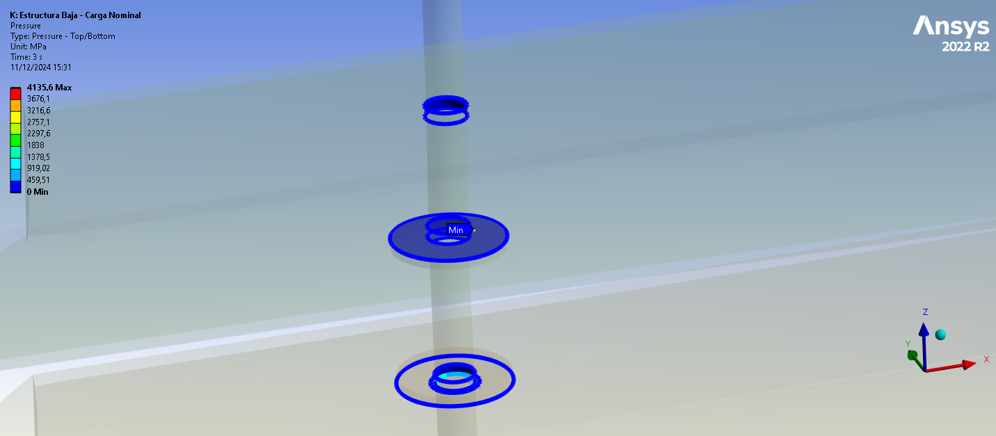
      "I am assuming you have selected the solid body as contact and shell body as target" Actually no, ANSYS would not let me do it this way, it says the contact is FAR OPEN no matter what pinball radius I assign. I´m gonna take a look at the Symmetric option for the contacts to see if I get results.

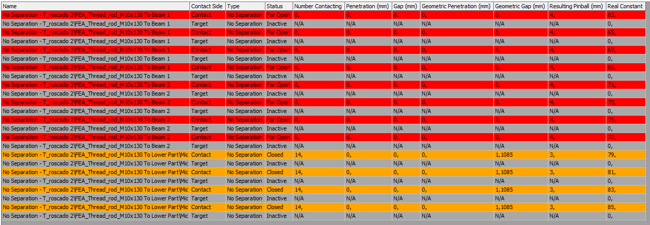
      "Also, I believe you have scoped multiple contacting pairs in single contact object, this is not recommended" I do have some like 2 contacts geometries to 1 target geometry, but like the 95% of the contacts are 1 to 1.

      "make sure that you have set Shell Thickness Effect to Yes" I started with this ON, but got problematic contacts not being detected in modal analysis and after I took off the thickness effect it worked fine. And yes, I selected the orientation TOP/BOTTOM accordingly.

      Thanks.

    • Kaushal Vadnere
      Ansys Employee

      Use of mid-surface does not necessarily over-simplifies the model, you are making an calculated assumption that the stress distribution in the thickness is not required hence you can avoid computationally expensive solid elements. For No separation contact types, the Far Open status means the penetration and gap is set to 0 even though there is some geometric gap exists at the contact interface. You can check geometry and adjust to touch. Shell thickness effect only considers the thickness of the shell for contact which means, when 2 bodies come into contact with each other, the contact will not accur at the mid-surface but at some distance from the mid-surface to account for the thickness of the shell. You can check parameters for the automatic contact detection or create manual contacts where contact is not detected.

Viewing 3 reply threads
  • You must be logged in to reply to this topic.