-
-
December 14, 2023 at 5:39 am
KANTUBHUKTA HEMANTH HARI KISHORE
SubscriberGreetings to everyone,
I hope you are doing well. I'm Hari Kishore, currently pursuing my Masters.
I'm doing transient analysis in ANSYS Maxwell to get the magnetic field distribution on the tube.
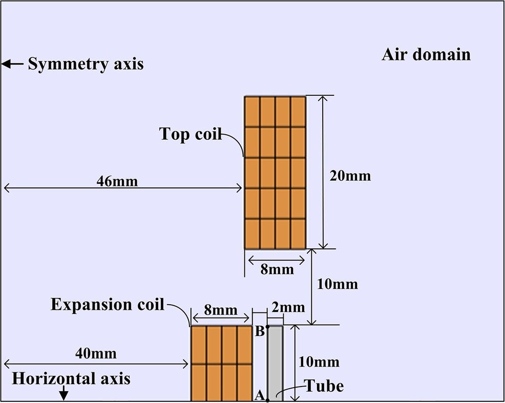
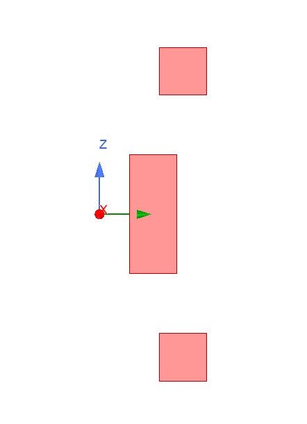
Here, the two-dimensional (YZ plane) symmetric geometry of the model is shown. The tube and expansion coil are 20 mm in length.
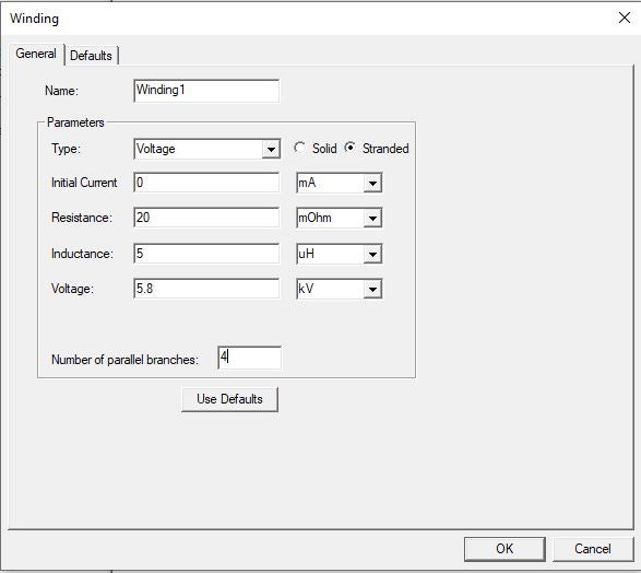
The expansion coil has an inner radius of 40 mm and an outer radius of 48 mm. This coil is made with a copper wire with a rectangular cross-section of 2 * 4 mm^2. (Y  * Z). Is it like the coil has 5 turns whose cross-section is 2 * 4 mm^2 (whose axis is in the Z-direction). And also, as we are seeing four such layers in the radial direction (Y-direction), are they connected in series? I want to excite this coil with 5.8 kV. How do I give coil terminals representing coil turns and layers, and how do I add them to the winding for a series connection? For each of the 2*4 cross-sections, do I need to assign a coil terminal and add all of them to one winding?
Thank you for your time and consideration. I will be thankful for your valuable suggestions.
Thank you in advance.
-
December 18, 2023 at 9:55 pm
GLUO
Ansys EmployeeHello,
Q:And also, as we are seeing four such layers in the radial direction (Y-direction), are they connected in series?
If the terminals are assigned to the same windings, the they are connected in series.
-
December 18, 2023 at 10:00 pm
GLUO
Ansys EmployeeQ: How do I give coil terminals representing coil turns and layers, and how do I add them to the winding for a series connection? For each of the 2*4 cross-sections, do I need to assign a coil terminal and add all of them to one winding? According to the picture, you have 8 2*4 coil terminals. For each terminal, it has 5 turns, so please use 5 as number of conductors. The 8 layers are connected in series, so please assign them to the same winding. There is another method that can handle complex connection clearly. Just assign one terminal per winding, then use the external circuit to connect the windings in the circuit scheme. GL -
December 20, 2023 at 5:33 am
KANTUBHUKTA HEMANTH HARI KISHORE
SubscriberHello GLUO,
Thank you for your response and information. Now, I understand how to give coil terminals and assign them to windings.
Also here, I want to know how the number of parallel branches in the windings works.
Â
What if I give the whole cross-section as a single coil terminal that has 5 conductors to represent 5 turns of the coil, and in the windings, as shown in the figure, the number of parallel branches is 4 (more than 1). Will it represent the same thing, or does the number of parallel branches have some other meaning?
Â
Thank you.
-
- The topic ‘To model coil geometry and assigning winding in ANSYS Maxwell’ is closed to new replies.
- How does Ansys Twin Builder implement different simulation steps for subcircuits
- Simulation of capacitor combining eddy currents with displacement currents
- Compute near field simulation with current
- Double-sided LIM external circuit error
- Ansys Resonance simulatioin error
- HFSS: Using Q3D to solve the DC point
-
3139
-
1007
-
918
-
858
-
792
© 2025 Copyright ANSYS, Inc. All rights reserved.