-
-
March 13, 2024 at 5:34 am
-
March 13, 2024 at 6:13 pm
danielshaw
Ansys EmployeeIt is not possible to provide a complete solution via this forum. I recommend that you submit a service case via the Customer Portal. Some thoughts:
1. If the mantle is very thin, have you considered representing it using shell or solid-shell elements?
2. Is the structure uniform out-of-plane? If so, have you considered using a 2D (probably plane strain) model? Even if the structure is not perfectly uniform out-of-plane, you might be able to adequately capture the behavior with a 2D approach.
3. Are the stresses developed in the mantle matrix critical? If not, have you considered using a very coarse mesh for that region. You would need to transition from the finer mesh near the mantle, but that transition should only require a few rows of elements. Why does your mesh seem to maintain the same density throughout the matrix mantle?
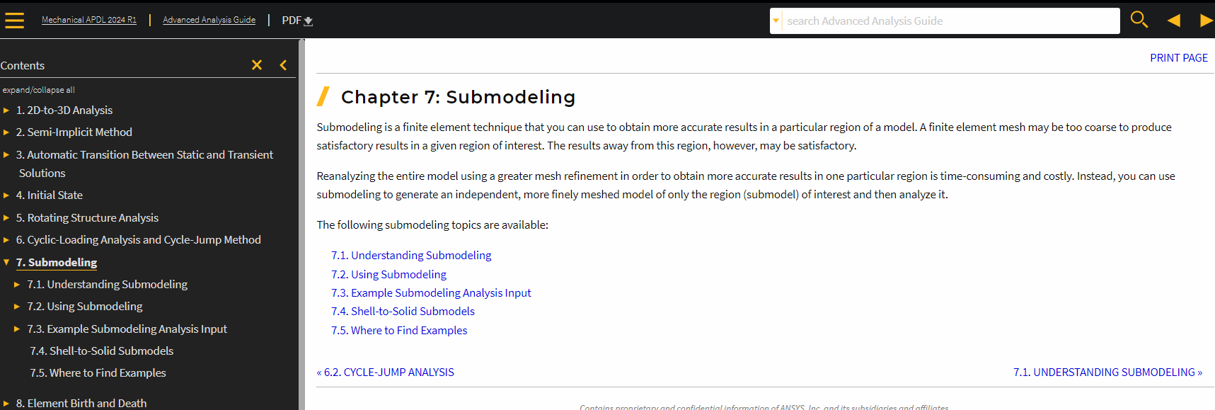
4. Have you considered using a sub-model (condensed part) to represent the mantle matrix? The base model could contain the mantle and a small portion of the mantle matrix, the remainder of the mantle matrix could be represented as condensed part. Even if you need to expand the condensed part to examine the stresses in the mantle matrix, the model should be manageable.
-
March 14, 2024 at 3:52 am
sachin.kumar
Subscriberthanks for your Response:
Actually I already discussed the same with ANSYS concerned person from India and we worked closely from last one month but did not get any success thats why I came to this portal.
1) currently doing 2D plain stress strain analysis. as per your understanding which one will be less computational expensive plain strain 2D or shell element??.
2) non-uniform
3) yes stresses are critical at the junction of mantle and matrix, as per field data failure is occuring at this.
4) sub-model: i have no idea about this could you elaborate how to use this concept??
-
March 14, 2024 at 11:45 am
-
March 15, 2024 at 4:14 am
sachin.kumar
SubscriberPl correct me if i am worng, As I understood firstly run full model at coarse mesh to generate the boundary condition at the cut section face or edge
in this strategy issue is to run full model to get the displacement at the cut interfaces and my model is too big to simulate even with coarse mesh.
but i will implement this strategy in radial direction.
let me know if you have any more suggestion
-
March 15, 2024 at 2:13 pm
danielshaw
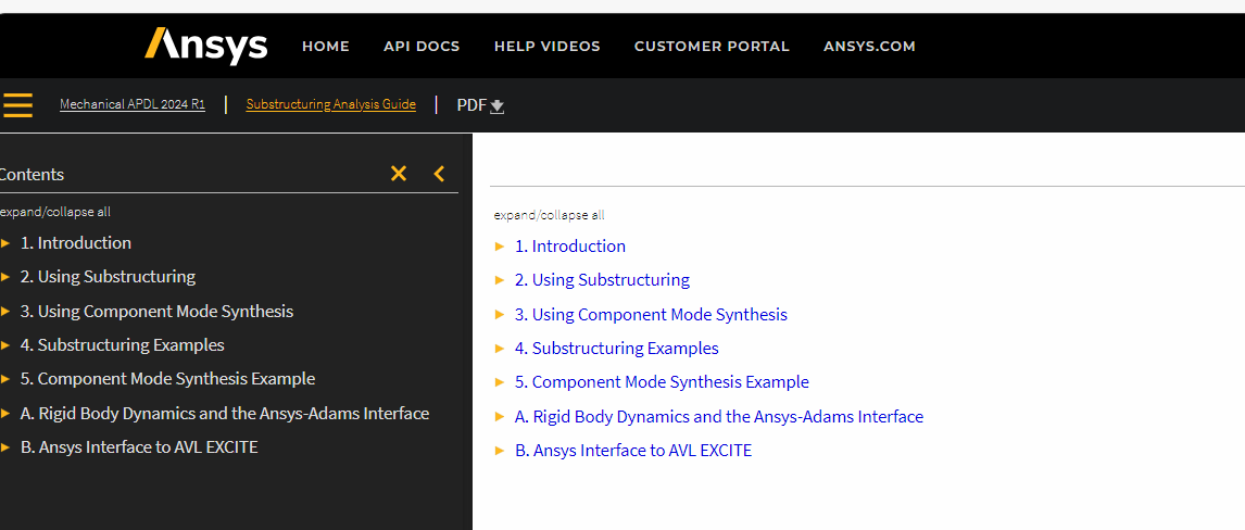
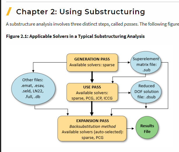
Ansys EmployeeNo. My apologizes. I directed you to the incorrect section of the MAPDL. I am not recommending that you try submodelling. I am recommeding that you consider using substructuring. See the MAPDL Substructuring Analysis Guide. With substructuring, you "condense" a portion(s) of the model into "superelements". The superelements have a reduced set of DOFs. You have the opton to later "expand" the superelements if you like.
-
- The topic ‘Thermo-structural failure analysis’ is closed to new replies.


-
4612
-
1515
-
1386
-
1209
-
1021

© 2025 Copyright ANSYS, Inc. All rights reserved.


