TAGGED: 2D, natural-convection, steady-state-thermal
-
-
December 2, 2024 at 6:20 pmJuhani ManninenSubscriber
Hi
I am trying to learn how to use Ansys Fluent for steady state 2D thermal analysis. I am attempting to simulate a situation where an electrical conductor generates heat, and the conductor is surrounded by an air-filled fluid region, which in turn is enclosed by a solid material (wood). It seems that natural convection is not working in the fluid region, and the heat does not appear to transfer from the fluid to the wood. Could someone advise what might be wrong? I have managed to simulate a similar situation with only an aluminum core surrounded by air, i.e., a solid-fluid setup.Here is some details:
-
December 3, 2024 at 12:15 pmRobForum Moderator
Why do you need interface zones? If they're not set correctly it'll not help. Then check air density.
-
December 3, 2024 at 8:07 pmJuhani ManninenSubscriber
Interface zones are generated automatically, I can't say if they are necessary. I believe the air density is correct since it works in the solid-fluid case that I previously managed to get working. Attached is an image of this earlier solid-fluid simulation. It is slightly larger in dimensions, but otherwise, it operates on the same principle. In that case, natural convection works, and the residuals converge. In the solid-fluid-solid situation, there is probably some boundary condition issue, but I can't pinpoint what it is.
Here is results of that solid-fluid case.
-
-
December 4, 2024 at 10:07 amRobForum Moderator
In a sealed domain you need ideal gas. Incompressible ideal gas would be the correct choice in an open domain.
Solid-fluid nonconformals are a little special and I'd avoid when learning to use the software. Read up on share-topology.
-
December 5, 2024 at 6:16 pm
-
-
December 6, 2024 at 10:20 amRobForum Moderator
OK. So the outer wall is fixed at 20C, but you're adding in some W/m3 to the centre solid? If you fix a flux AND the temperature what might happen? Hint: read up on what the convective wall option does.
-
December 7, 2024 at 1:56 pmJuhani ManninenSubscriber
I do understand the situation where the outer wall temperature is fixed. The color gradient difference in the wood is not very large, but when inspected with a probe, there is a temperature difference between the inner and outer surfaces of the wood. This means that heat transfer occurs between the fluid and solid domains in that area, even though at a quick glance it may seem otherwise. The effect of natural convection initially appears not to work, but on closer inspection, the temperature above the aluminum domain is higher than below it, so natural convection works at least somehow.
What puzzles me is why the K-residual doesn't converge. Can the result still be correct even if not all residuals converge? I refined the mesh for greater accuracy, but I didn’t notice any significant difference. Could it be that the calculation model is not suitable for analyzing such a small fluid domain, or is it really the case that natural convection behaves like this in reality?
I also created a model with the same parameters but with a larger fluid domain, where natural convection behaves at least in my opinion “correctly”. In this case, the denser and lighter air masses clearly redistribute under the influence of gravity, and the K-residual also converges now.
-
-
December 9, 2024 at 11:53 amRobForum Moderator
The lower image shows the buoyant plume nicely, assuming that's a contour of temperature. I can't read the text as it's too small.
Convergence is not just residuals. It's also monitor points (is the solution changing) and fluxes (does what goes in come out). So in this case it's very likely the residuals won't look good. You may well have a transient effect in the flow, additionally the answer may not be too far off the initial condition (for some fields) so the residual maths can't reduce the error.
-
December 9, 2024 at 5:47 pmJuhani ManninenSubscriber
Yes, the contours represent temperature, image can be enlarged by zooming in on the page. This was a hypothetical situation to get started and understand how such a case is defined, but I’ll need to look into the convergence issue more closely if it turns out to be a problem.
Does Ansys have a similar feature to Comsol's Infinite Element Domain that could be defined around such a cable conduit to model the soil, so there's no need to define a massive soil domain?
-
-
December 10, 2024 at 11:52 amRobForum Moderator
The convergence shouldn't be a problem, it just needs to be understood.
For the soil. We don't have an infinite element type but I'd generally coarsely mesh some region and look at fixed temperature bc's.
-
December 18, 2024 at 3:26 pmisaac.galeana.trujilloSubscriber
Hi,
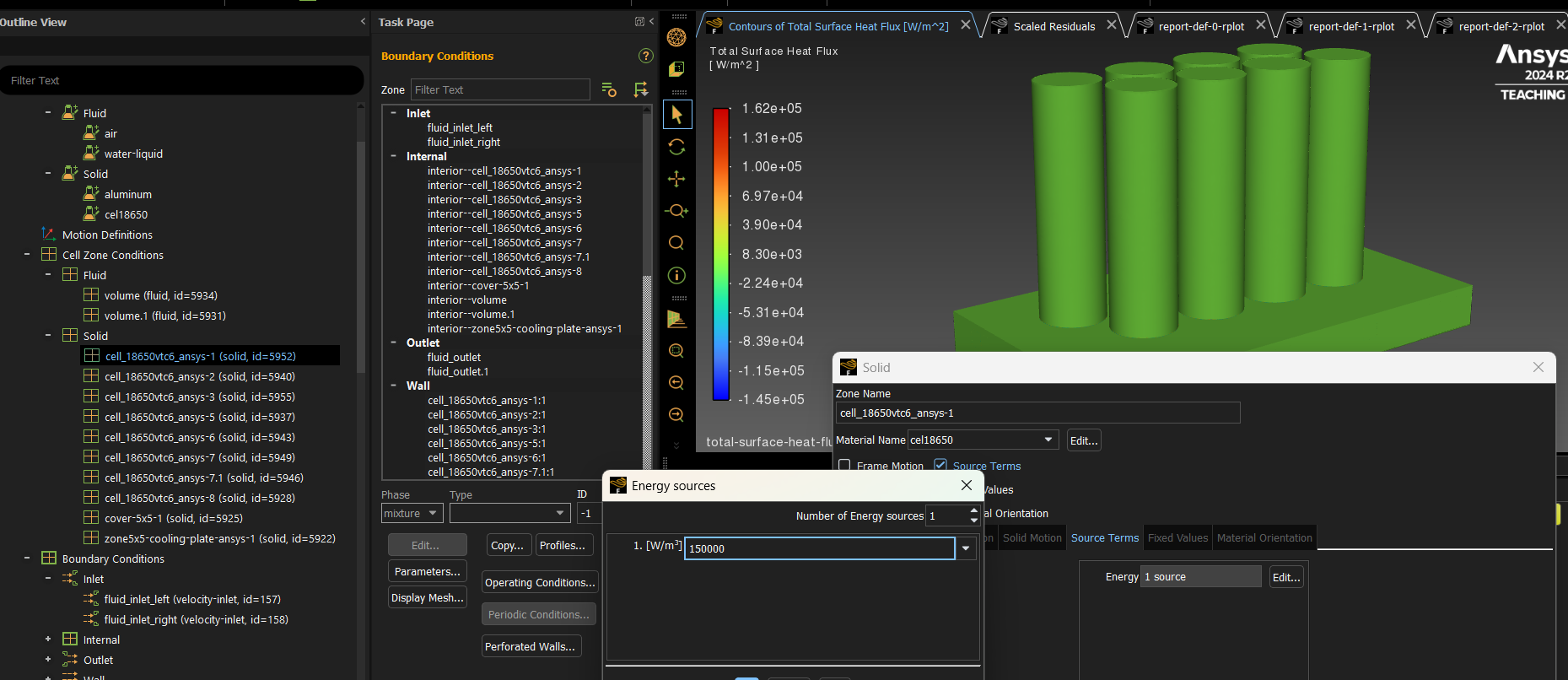
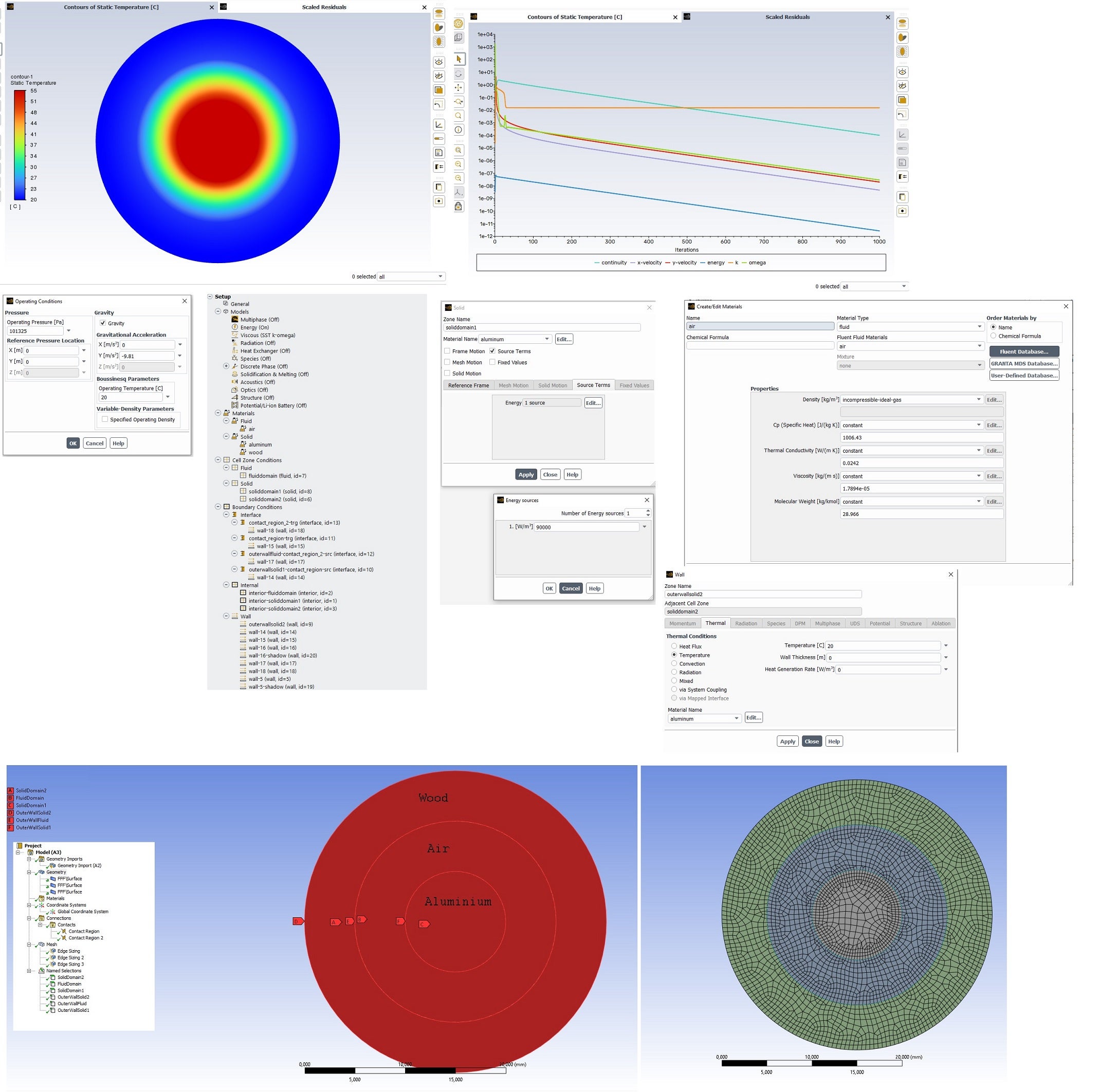
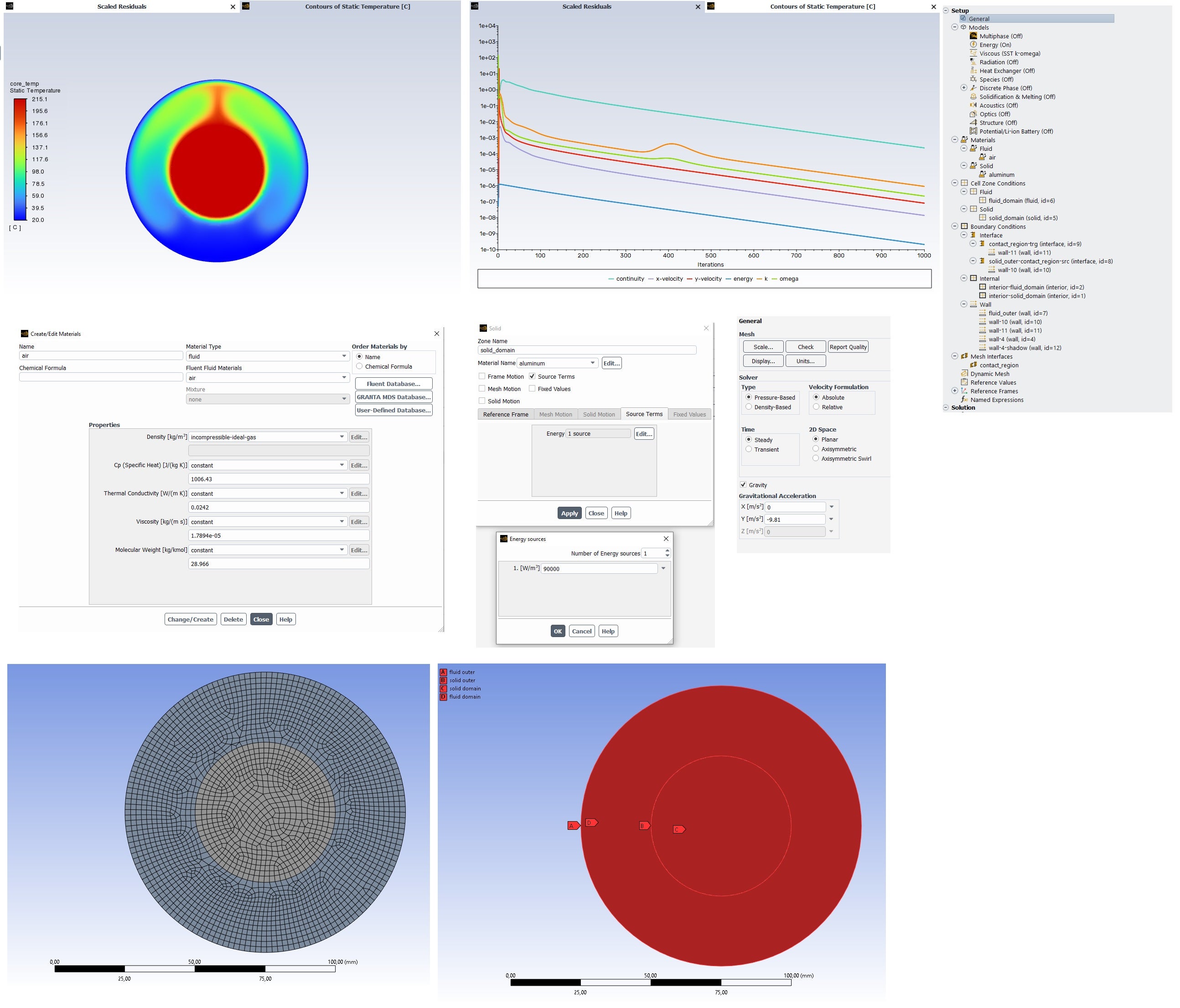
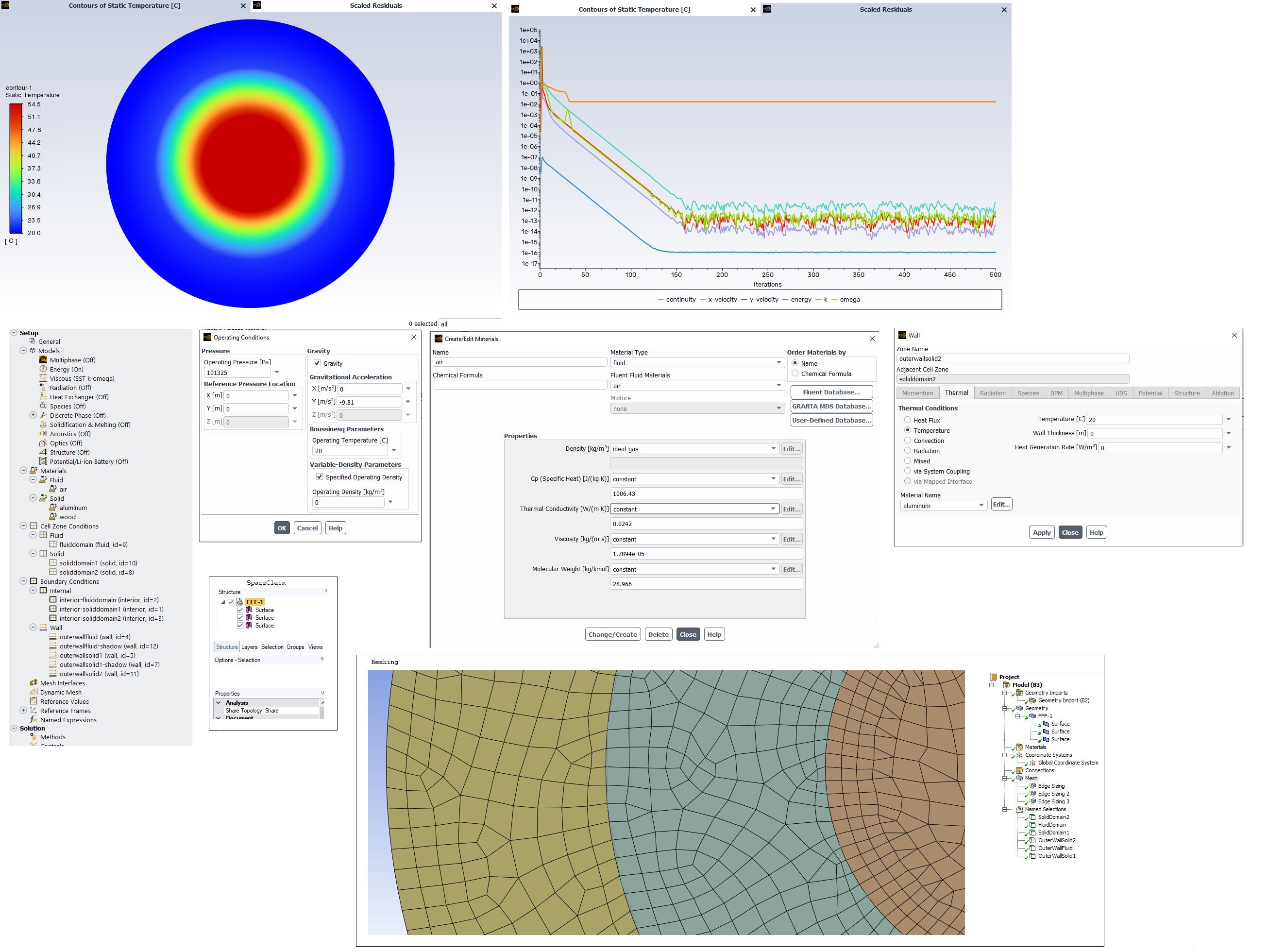
I need help. I am running simulations in Ansys Fluent to determine the heat dissipasion capacity and behaviour of a baterry thermal management system, the heat is never transfered among the parts (cooling plate, cover, fluid).
I have created Named selections (channels's faces, fluids' faces, colling plate faces, cells contact area with the cover, cover contact areas with the cells and cooling plate).
I have set BC and the cell zone conditions, materials, heat generation rate for the cells and during/after simulation the contours show no heat transfer through the components.
I have tried tried w/wo the tool Share in Spaceclaim, adding and deleting Named selections, etc. but nothing works. I don't know what I am doing wrong.
Could you have a look and tell me what I am doing wrong?
-
December 19, 2024 at 4:43 pmJuhani ManninenSubscriber
Is the model at ambient temperature, or does its temperature just rise very high? How have you defined how thermal energy is transferred away from the model?
-
-
December 19, 2024 at 5:58 pmisaac.galeana.trujilloSubscriber
I considered the cooling plate adiabatic (so no heat transfer to the ambient). The temperature is normally rise in the cells (which are the heat generators) and the heat should be transfer by conduction to the cover and then from the cover to the cooling plate and fluid. The cooling plate has 2 channels, with two inputs and outputs, since the fluids have a velocity and it is constantly running, heat should be absorved and take away via the fluid by convection. I didn't add any heat convection coefficient, insted I added the fluid velocity, so Ansys should calculate the convection coefficient based on the velocity, input temperature and fluid properties.
-
December 20, 2024 at 5:29 pmJuhani ManninenSubscriber
Ok, i haven't done that kind of simulation, so I can't directly say what the problem might be. It's probably a good idea to start a separate thread about this and explain in detail what you've done and how the model is defined.
-
-
- You must be logged in to reply to this topic.
- How do I get my hands on Ansys Rocky DEM
- Non-Intersected faces found for matching interface periodic-walls
- Unburnt Hydrocarbons contour in ANSYS FORTE for sector mesh
- Help: About the expression of turbulent viscosity in Realizable k-e model
- Script Error
- Mass Conservation Issue in Methane Pyrolysis Shock Tube Simulation
- Facing trouble regarding setting up boundary conditions for SOEC Modeling
- convergence issue for transonic flow
- Running ANSYS Fluent on a HPC Cluster
- Point exception in erosion calculation
-
1882
-
802
-
599
-
591
-
366
© 2025 Copyright ANSYS, Inc. All rights reserved.