-
-
April 24, 2025 at 9:10 am
fan134
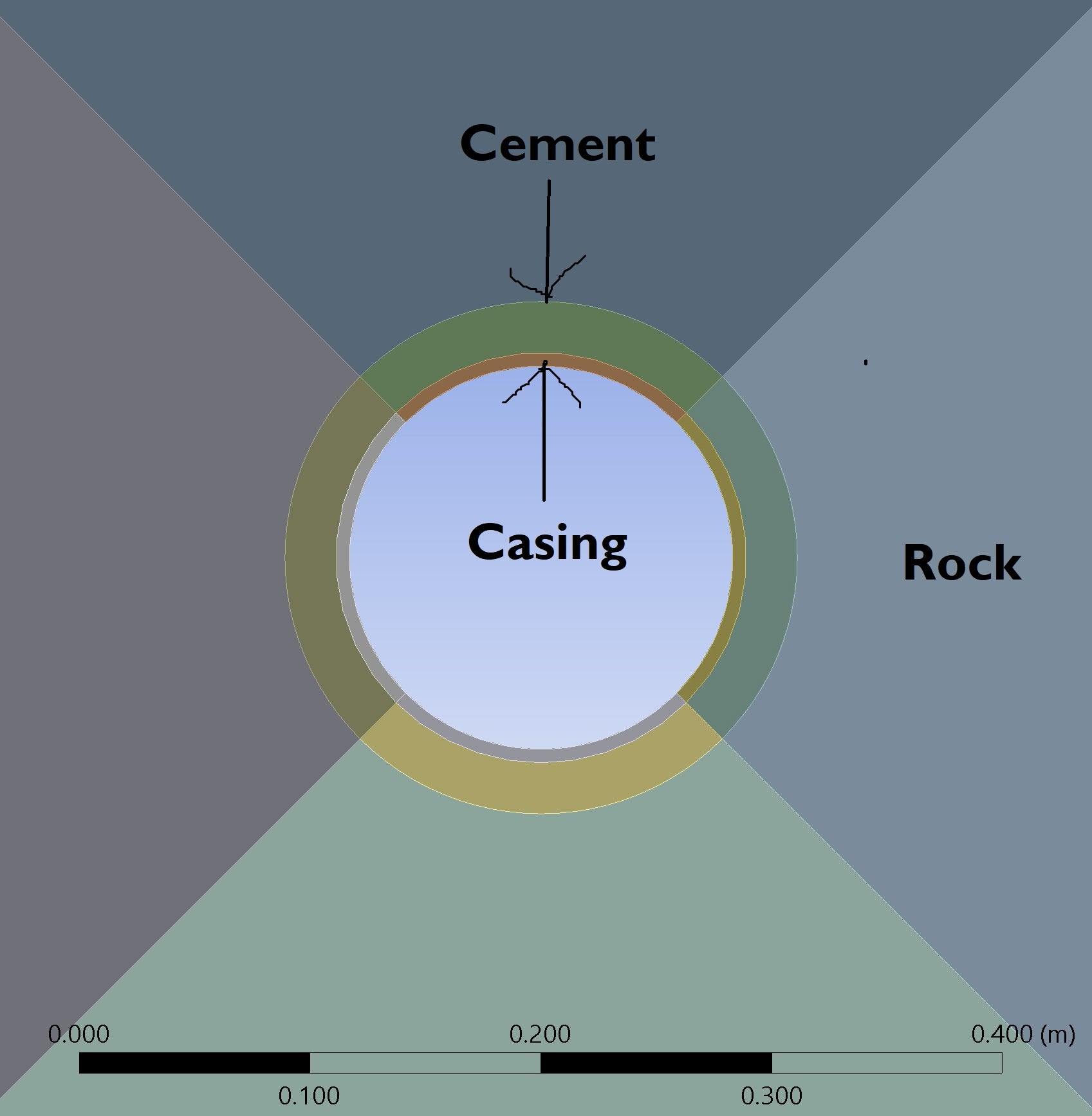
SubscriberMy 3D static structural model consists of three bodies (as shown in the attached figure): the innermost body is the casing, the outermost is the rock, and the cement is positioned between them.
When I attempted to create a semi-elliptical fracture on either the inner or outer face of the cement—located at the casing–cement or cement–rock interface, respectively—the meshing process failed. To address this, I changed the shared topology option in Design Modeler from “Automatic” to “None,” which allowed me to generate the mesh. I also set the batch connection to “Yes” to create a conformal mesh.
However, the solution terminated with the following errors:
*** ERROR *** CP = 62.594 TIME= 02:45:05The command (CINT,SURF) supports only the 10-node tetrahedral element type(SOLID187) when UMM is on. Please turn UMM off (CINT,UMM,OFF) orremove the command (CINT,SURF) for crack set 1.*** ERROR *** CP = 62.594 TIME= 02:45:05The command (CINT,SURF) supports only the 10-node tetrahedral element type(SOLID187) when UMM is on. Please turn UMM off (CINT,UMM,OFF) orremove the command (CINT,SURF) for crack set 2.As suggested, I used the following APDL command in the fracture definition:
CINT,UMM,OFFHowever, after doing this, the solver gets stuck at 16% with the status "writing results," and it doesn’t progress even after a couple of hours. For reference, my mesh contains 32k elements. Previously, without the fracture, I was able to run a model with over 100k elements, which completed in 10–15 minutes.
I would greatly appreciate any suggestions or guidance on how to resolve this issue.
-
April 24, 2025 at 9:31 am
Erik Kostson
Ansys EmployeeHi
Are you trying to model a crack in the cement?
All the best
Erik
-
April 24, 2025 at 10:01 am
fan134
SubscriberHello Erik,
Yes I'm trying to model a crack in the cement. I would really appreciate if you could guide me to resolve the issue.
Best Regards,
Faysal
-
April 24, 2025 at 10:45 am
Erik Kostson
Ansys EmployeeHi
Cracking in concrete using say our fracture tools like you are trying to do would be very hard and not sure if it would be the correct way of doing this (not seen any cases on that).
What one can use to capture damage in concrete is the MW or microplane models – see the help manual where there are several examples on concrete.
Chapter 54: Reinforced Concrete Joint Analysis
Hope this helps.
All the best
Erik
-
April 25, 2025 at 12:34 am
fan134
SubscriberHello Erik,
Thank you for your reply. I'll definitely look into the microplane model. However, before that, I want to resolve the current issue. The problem I'm facing doesn’t seem to be related to the material, because I tested it by changing the material assignment of the middle body from cement to structural steel, and the issue still persists.
Do you have any suggestions on how this can be resolved?
Best Regards,
Faysal
-
- You must be logged in to reply to this topic.


-
3019
-
970
-
857
-
761
-
599

© 2025 Copyright ANSYS, Inc. All rights reserved.


