-
-
July 4, 2023 at 7:00 pm
Aavash Budhathoki
SubscriberHello everyone,
I am trying to simulate the results of a tensile test using Ansys. My research advisor has provided me with the UTS, 0.2% yield strength, elastic modulus, and Poisson's ratio value for four specimens with different build combinations. I entered the values manually and created new materials in the materials library. Then, I proceeded to use Explicit Dynamics with the following parameters:
Mesh size - 0.001m
Fixed boundary condition, displacement - 0.03 m in 0.001 s
Despite having entered 27 MPa as the ultimate tensile strength value, the stress in the model exceeds that value without any signs of failure. I have been trying to replicate the experimental results for two weeks now but to no avail. I would be highly grateful if I could receive some assistance in this matter.
-
July 5, 2023 at 12:43 pm
Ram Gopisetti
Ansys EmployeeHi,
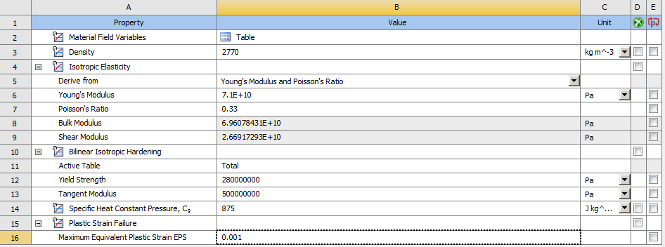
you have deficint material model, UTS, 0.2% yield strength, elastic modulus, and Poisson's ratio are not sufficitent , you also need to model the plasticity definition, your material model should look like as follows (ideal, example)
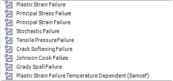
you need to use an failure critieria from the engineerign data as follows
then you need to make sure that the failure is used by mateial not of geomentric strain limit
cheers, Ram
-
October 21, 2023 at 1:26 pm
Desi Gustiani
SubscriberCan you explain to me about Displacement in the tensile test and where the numbers I should input come from?
-
October 22, 2023 at 9:59 am
Sampat Kumar
Ansys EmployeeHi Desi,
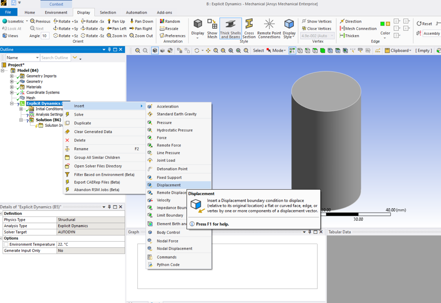
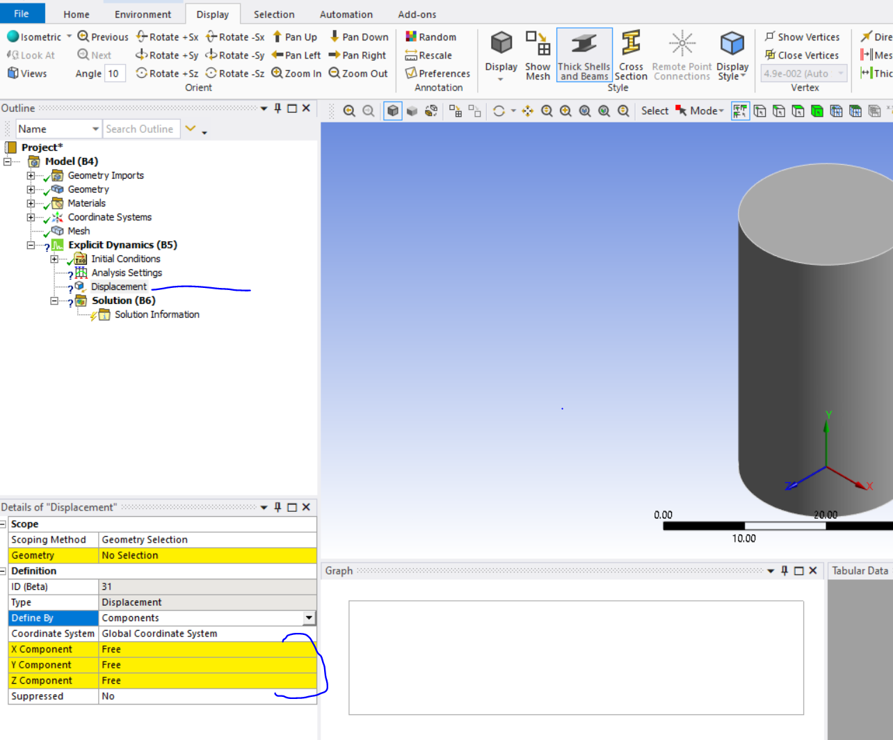
You can right click--> explict dynamics--> select the displacement--> enetr the value in the x, y or z component. I attacheed the screenshot here.

as per your query, I got to know that you were asking how to enter the value.
for more details about the displacement and force, please follow the attached link.
https://ansyshelp.ansys.com/account/secured?returnurl=/Views/Secured/corp/v232/en/wb_sim/ds_Displacements.html
https://ansyshelp.ansys.com/account/secured?returnurl=/Views/Secured/corp/v232/en/wb_sim/ds_Force_Load.html
Regards,
Sampat
-
-
October 22, 2023 at 11:08 am
Desi Gustiani
SubscriberThank you Mr Sampat, how about the value should I put in X Y or Z component ?
-
October 22, 2023 at 11:15 am
Sampat Kumar
Ansys EmployeeIt's the value of the displacement in the corresponding direction. If you want to enter the value in the x direction, then enter the value there. If you want to restrict the other direction, then you can enter 0 there. If you want to keep them free, then keep them free. It all depends on the boundary condition that you want to apply.
Regards,
Sampat -
October 22, 2023 at 11:20 am
-
-
- The topic ‘Tensile Testing via Explicit Dynamics’ is closed to new replies.


-
4818
-
1587
-
1386
-
1242
-
1021

© 2026 Copyright ANSYS, Inc. All rights reserved.


