-
-
March 12, 2024 at 3:15 am
Bibek Kafle
SubscriberI am trying to model a uniaxial tensile test on lattice structure surface coated by the metal layer (within elastic range i.e linear analysis). I created lattice geometry using shell feature available in ANSYS spaceclaim, then surface body was created copying all faces in ANSYS Spaceclaim. Then I used share topology between surface and solid body to ensure a conformal mesh between them.
Can I use share topology between surface and solid bodies??
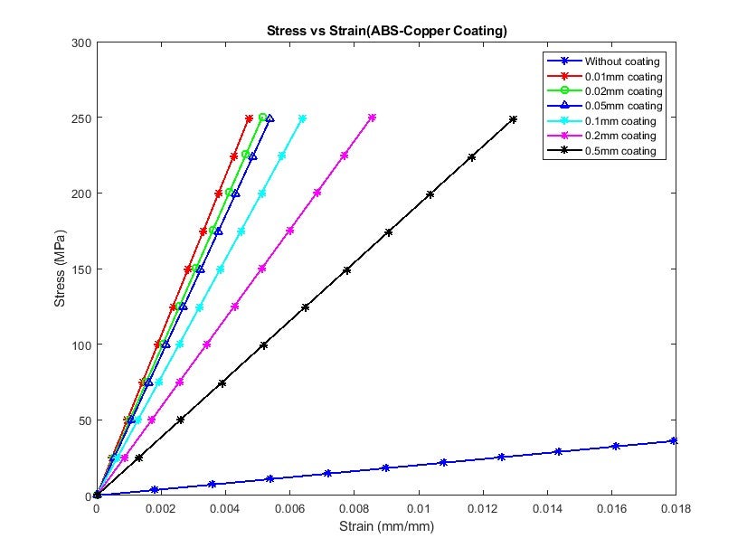
I am trying to determine the combined modulus of the model, for which I have plotted max. equivalent stress and Total equivalent strain in the model using time stepping and calculate slope of the graph to get combined modulus.However, I am getting maximum stress value at metal coating and Max. total strain value at plastic body both at different locations.
Is there any way I can verify my results with hand calculations?
I would really appreciate it if anyone could provide me with advice on this.
Thank you !!
-
March 19, 2024 at 2:22 am
mjmiddle
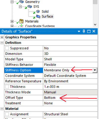
Ansys EmployeeShared topology between solids and surfaces is a bad idea. The surfaces have shell elements with 6 degrees of freedom, and the solid elements have 3 degrees of freedom. In my experience the results may not be accurate because of this. You can turn off the rotational degrees of freedom on the shells by setting the "stiffness option" to "membrane only." This may be reasonable for thin coatings and especially material that is a lot softter than the volume body material.
If you have a metal coating, it may contribute significant bending stiffness, so turning off bending on the surface may not be reasonable.
You should make sure to set the "Offset Type" to the side that shows correctly in the mesh.
Also make sure you are using the same linear/quadratic setting for the surface body as the volume body. Either set on global mesh object in Outline or on mesh methods.
Other ways to do this is through bonded contact instead of shared topology, or do not model the surface body in SpaceClaim at all. Instead insert a "Surface Coating" in Mechanical:
-
March 19, 2024 at 3:39 am
Bibek Kafle
SubscriberThanks for your feedback.
I am currently using membrane only for stiffness option with bottom offset. Since load is applied only in axial direction, I thought bending stiffness can be neglected, can I do that for this lattice structure?
And Isnt surfacing coating feature similar to creating shell bodies with shared topology?
-
March 20, 2024 at 9:53 am
mjmiddle
Ansys EmployeeYou have a scissors type structure which will certainly experience bending in some locations. The "bottom" offset is model dependent. View the mesh to see what side elements appear. Yes a surface coating is similar to shells with shared topology, but it should do it properly.
I see a "Stress tool" scoped to a surface coating gives zero results, so I submitted a defect report on that.
-
- The topic ‘Surface Coatings’ is closed to new replies.


-
5094
-
1831
-
1387
-
1248
-
1021

© 2026 Copyright ANSYS, Inc. All rights reserved.


