Fluids

Fluids

Topics related to Fluent, CFX, Turbogrid and more.

SUCTION LIFT TIME ANALYSIS

    • msm19b039
      Subscriber
      hELLO THERE. Kindly help me out. Im modelling the suction operationality of a pump connected to a pipe with pressure inlet at the pipe start(sump). 
      The impeller starts rotating, this creates suction and less pressure and on the other side of the nrv is pipe which is connected to the sump (inlet), this is at atmosphere pressure. This pressure difference shall open up the nrv gradually and them the water starts rising from the sump replacing the air in the pipe. Without the nrv open, the water wouldn't lift up(right?)
      Now to model the nrv behaviour, I specified a small zone near pump inlet as porous media zone with a high viscous resistance and thought that I will decrease this gradually (letting more flow in) as the pressure difference rises. All good. But as soon I start the simulation, fluent reports negative absolute pressure all inside the pump.
       
      I want a realistic behaviour wherein pressure drops inside pump. Nrv opens up. Water rises from sump displacing the air inside the pump. And I just want to know the time It'd take the water to each the pump inlet. 
      Please guide me
    • Ahmed Hussien
      Ansys Employee

      Did you enable a multiphase model in your setup? In this type of scenario, cavitation is likely to occur, especially during the initial pressure drop, which can explain the negative absolute pressures you're seeing inside the pump.

      To model this behavior realistically, make sure to use a multiphase model with cavitation mass transfer enabled. This will help properly account for phase change and prevent unphysical negative pressure values.

    • msm19b039
      Subscriber


      I apologise for the lack of specified information. I actually made another detailed post. However I didn’t receive any reply on that.

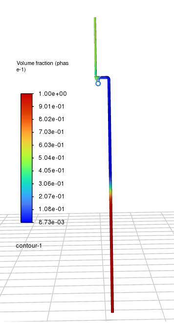
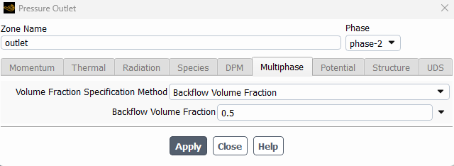
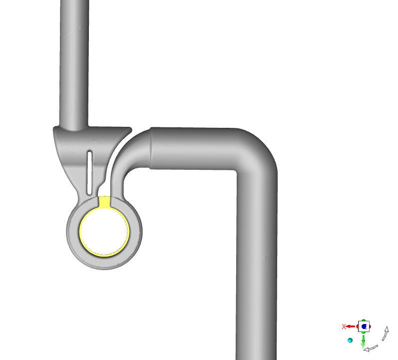
      Yes, I’m using a multiphase VoF model. With pipe being patched with air and the pump with water (primed initially). I have a few clarifications and maybe the error lies there:


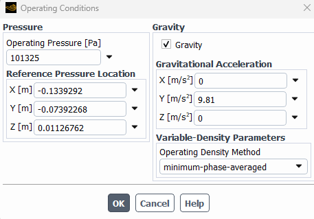
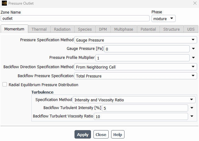
      1) Could it be an issue of operating conditions specifications. I’ve  given operating pressure of 101325 (and consequently 0 Pa Guage at boundaries) and given specified operating density of 0. Reference pressure location of (0,0,0) by default. I’ve read operating conditions are critical in multiphase flows and also where hydrostatic pressure is involved. Does any of this seem wrong?


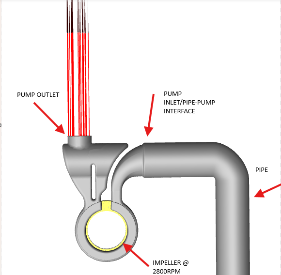
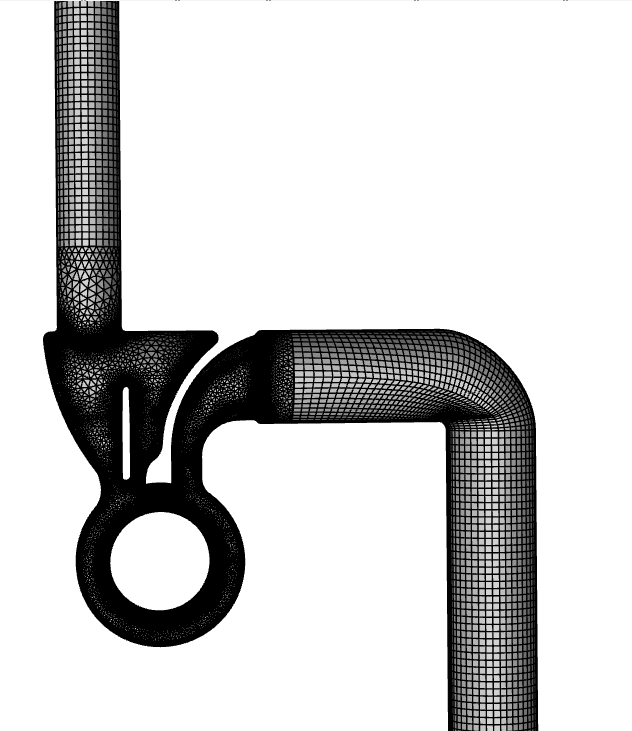
      2) Is porous media with resistance coefficients actually a good way to mimic the nrv? Or an inlet/outlet vent with pressure dropping coefficient makes sense? Please guide.


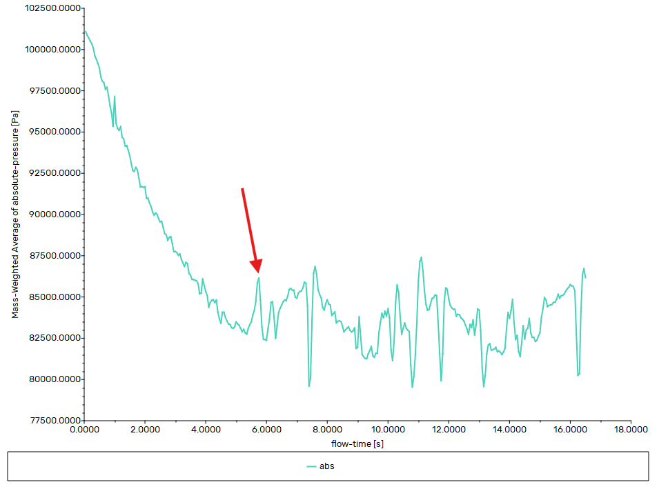
      3) I have one intuitive doubt here. If negative absolute pressures are being created in 0.2/0.3 seconds that implies the suction is so high and valve opens in just 0.2-0.3 seconds? The cracking pressure is somewhere around 20k Pa. Or is my understanding wrong? Like if the pressure becomes so low so quick then the nrv opens up right? But I don’t think that’s how fastly it opens up in real life. 


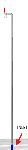
      And say for a very simplistic scenario or full open nrv I.e. no explicit nrv behaviour to be imitated and it is just regular interface between pipe/pump. Even then the suction lift time for 3 metres comes to be around 5-6 seconds whereas the real life time is 35 seconds. Even when accounting for the nrv behaviour, I'm still way behind the result. Could this possibly be due to improper hydrostatic pressure settings?


      Please guide me. I’m going Oppenheimer over this. 


      Please tell the best way to mimic this real life behavior in a simpler way.


      Thank you for your time. I’m grateful. 


    • Ahmed Hussien
      Ansys Employee

      First, make sure to enable cavitation modelling to prevent unphysical pressures.

      Regarding your points:

      * Operating Conditions: Using 101325 Pa as operating pressure is fine, but ensure gravity is enabled and the reference pressure location aligns with the liquid level.

      * NRV Modeling: Porous media can work, but a pressure jump boundary might better reflect realistic NRV behavior, especially if you know the opening pressure (~20 kPa).

      * Fast Valve Opening: If Fluent shows negative absolute pressure early (~0.2 s), it's likely due to:

         - No cavitation model (allowing unphysical pressures)

         - The valve opening too quickly (low resistance)

    • msm19b039
      Subscriber

      Thank you Ahmed for your reply.  Lets split the issue into 2 segments and solve each of them. I believe I'm almost there and would need only streamlined guidance from you.


      1) I keep aside nrv for now at least and model the pump/pipe interface as regular full open. Pressure BCs at boundaries. Pump patched with water. Air in pipe. I start the simulation with impeller running at 2800 rpm, the Pressure drops at suction according to rho*g*h as the water rises and the water reaches the interface in roughly 5 seconds. Say nrv opening time would make 8 seconds. But the real life value is 35 seconds. Why? Would there be a need to introduce cavitation model here as well? 


      I once read on ansys innovation post that the reference pressure location should be at a place of one constant fluid in multiphase flows and if there's no one constant fluid anywhere then ideal gas law needs to be activated. 


      2) Nrv behaviour. I'd sat let's accomplish '1' first and then we can move onto this. 


      Thank you for your time sir. 

    • msm19b039
      Subscriber

      Hello Ahmed. As per your direction, I turned on the cavitation model and established it between the phases of water-liquid and water-vapor. I set the operating pressure to 101325 Pa, specified operating density to zero and the reference pressure location to liquid level. 

      My simulation runs really well and I do see water being lifted up by the pump and the absolute pressure keeps dropping near the pump pipe interface from 101325 Pa as per the rho*g*h value. 

      However after a certain number of iterations, reversed flow starts at the outlet, followed by inlet and consequently the pressure at the pump/pipe interface doesn't drop anymore(gets unstable and stagnant) i.e. the water doesn't get lifted up. 

      I tried extending the domain outlet boundary by increasing the length of the discharge pipe but reversed flow persists. This is the only issue that is stopping me from getting the suction lift time. I believe resolving this would help me in getting accurate results. Please guide.

      The discharge pipe mesh is structured quad elements and the quality of the mesh is good. I'm attaching a few images for your reference

      Also I standard initialized from the volute and not the inlet. I was reading on another platform that it could possibly be a reason. Another thing is the backflow direction is set to 'from the neighbouring cell' in outlet bc.

      Please help me counter this issue. I'm confident I will be able to get positive results if this is resolved.

    • Ahmed Hussien
      Ansys Employee

      Do you expect the water to fill the entire domain? If so, you can initialize the domain with water accordingly. Also, keep in mind that if the pump is located at a higher elevation, it may lead to cavitation. The extent to which the water rises will depend on the pressure difference or the pressure applied by the pump.

      Additionally, please double-check the direction of gravity in your setup. I noticed it is currently set in the positive Y direction—make sure this reflects the actual physical setup. You may need to set it to -9.81 m/s² if gravity should act downward.

    • msm19b039
      Subscriber

      Yes, eventually the water fills up the entire domain. But initially, only the pump is filled with water(primed) and suction/discharge pipes have air. 

      You want me to initialize the entire domain with water? i.e. patch water everwhere?

      Yes, and I have enabled cavitation between phase 1(water) and phase 3(water vapor). From experimental data, I already know that this particular pump can raise from even 7m and I'm modelling only a 3m pipe.

      I believe my direction specification of gravity is right? please see the image

      Looking forward to a fast reply.


      Thanks much for your humble service.

    • Ahmed Hussien
      Ansys Employee

      You can try initializing the entire pipe with water to check whether the pump provides sufficient pressure to raise the water to the desired height. Also, how did you model the pump — are you simulating its actual rotation, or using a simplified approach like a pressure jump or momentum source?

      If cavitation occurs and air is present, you’ll end up with a gas mixture of air and water vapor. In that case, you may need to enable the species transport model to properly account for mixing. As a simpler alternative, you could remove air and retain only water vapor as the secondary phase, which can help simplify the simulation while still capturing cavitation effects.

    • msm19b039
      Subscriber

      Yes Ahmed, I'm simulating the actual rotary effect of the impeller. I'm utilizing mesh motion for the impeller with 2800 rpm and proper rotation axis (clockwise direction). 

      As of now, I'm modeling without any sort of valve behavior to make it simpler so cavitation is very abysmal as no "vaccum" is created and the residual of vof phase 3 (water vapor) drops to e-20. 


      The pressure at pump/suction pipe interface keeps dropping from 101325 as per rho*g*h where h is the rise of water. After reaching a value of 82000 it doesn't drop anymore and just terribly gets stagnant there with reverses flow at outlet and inlet warnings.


      I believe reversed flow is natural and very physical in this case? There is no gradient near the outlet or enough momentum to drive the fluid outwards and flow reverses and sort of acts as a head reversal which builds up local pressure thus leading to reverse flow near inlet too. 


      Don't you think this is what would be happening in real life too? The pump ejects the primed water and this water reverses after going to a certain height and more or less oscillates at that position and thus the air above it also doesn't drive outwards from the outlet. Maybe at 85k Pa abs pressure the water gets almost ejected out and their is reversal and pump is operating on a mixture dominant by air and thus it gets difficult for the pump to lift water? 

      From experiments too, the suction lift for 3m is 35 sec, for 5m 170sec and for 7m nearly 230 sec. In my simulation reversed flow starts around t=6 sec. Maybe I need to run the simulation for much longer? What is your opinion.


      As of now, I changed the outlet to mass flow outlet with very small value (0.005 kg/s) for phase air. So far, there are no reversed flow Warnings but could arise later on. 


      Please guide

Viewing 9 reply threads
  • You must be logged in to reply to this topic.