TAGGED: peteroznewman
-
-
March 29, 2022 at 10:32 am
tumulpurwar
SubscriberHello peter
For local vibration analysis, when local structures are in contact with fluid, the added mass effect of the fluid must be considered in the calculation. The added mass can be considered either through virtual mass method using boundary element method (BEM) such as ‘MFLUID’ card of MSC NASTRAN or using empirical formulas.
How to get added mass from Ansys aqwa, when I don't have complete ship, just portion of ship to do local vibrational analysis?
March 29, 2022 at 9:58 pmpeteroznewman
SubscriberSeveral discussions on this site have asked about vibrations of a tank structure filled with water. The water can be meshed with fluid elements and a Fluid-Structure Interface FSI can be defined between the fluid and the tank wall which is meshed with structural elements. The link below is a Google Search result page with links to many of those discussions.
https://www.google.com/search?q=site%3Aforum.ansys.com+water+tank+structure+vibration+modal
March 30, 2022 at 10:44 amErKo
Ansys Employeeto further clarify.
Ansys in general does not have an equivalent MFLUID like capability to account for the fluid added mass.
(as a side Aqwa is not suitable for doing what you need (investigate the vibration of submerged structures))
They way to do what you describe with an Ansys product, is to use Ansys Workbench (Mechanical Modal Acoustics or Harmonic Acoustics) which can account for the fluid added mass. This is done in practice by modelling and meshing the water with acoustic elements (FLUID220/FUID221 and FLUID30), which are then connected with the structural elements (say of a submerged steel structure). For more info on this approach search the forum for fluid added mass (I have written a few times about this and you should see how this is done in practice).
As I said this is not similar to the mfluid approach as we use acoustic elements to represent the actual fluid and the fluid added mass on to a structure, but it is the way we can do this. Hope you still find this info. useful.
Regards
Erik
March 30, 2022 at 11:58 amtumulpurwar
SubscriberThanks Peter & Erik
May i know why aqwa cant be use for my problem?I have a yacht hull, i want do vibration analysis of that hull, but i have to consider added mass, on that part of hull, where it is coming under water/sea.
What i know & heard, i can calculate added mass through Aqwa in abscence of viscosity offcourse
Could you explain the reason" (as a side Aqwa is not suitable for doing what you need (investigate the vibration of submerged structures))" over it.
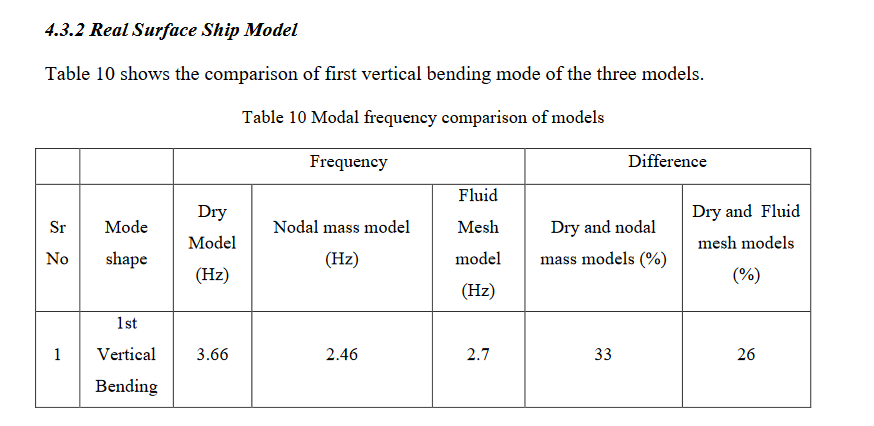
Would also like to know difference between Nodal mass based vibration simulation and Fluid mesh based simulation.
Sure Fluid based mesh i understand, is Nodal mass model more for APDL?
Regards
Tumi
March 30, 2022 at 1:11 pmErKo
Ansys EmployeeHi
So Aqwa is a hydrodynamic panel code for the analysis of ships (ship dynamics/motion), and it is not for vibration analysis of ships or ship like structure - thus different to the mfluid command which is to calculate the fluid added mass for vibrating submerged structure - so it can not be used for the vibration analysis for submerged shell structure and it does not have the capability to generate the fluid added mass on say a shell structure such as a ship. No we can not give any more advice here on the differences (we can not provide any more detailed explanation of the difference since mfluid is not an Ansys capability), but I hope this is clear and is enough. Should you wish to investigate yourself, please see the Aqwa help and theory manuals .
As I am Ansys employee and have investigated these capabilities of capturing wet mode of submerged structures, and based on my experience in this field so modelling the global vibrations of submerged structure (e.g., ships), the only approach that you can use with an Ansys product for this type of analysis, is as I described above the following:
' to do what you describe with an Ansys product, is to use Ansys Workbench (Mechanical Modal Acoustics or Harmonic Acoustics) which can account for the fluid added mass. This is done in practice by modelling and meshing the water with acoustic elements (FLUID220/FUID221 and FLUID30), which are then connected with the structural elements (say of a submerged steel structure). For more info on this approach search the forum for fluid added mass (I have written a few times about this and you should see how this is done in practice).'
site:forum.ansys.com vibration and mass and water and ekostson - Google Search
Finally we do not have anything specific for calculating fluid added mass called nodal mass so I can not help here.
We also do not have anything called fluid mesh - what we have is the above workflow for getting the fluid added mass which is using acoustic finite elements for the fluid.
https://www.google.com/search?q=site%3Aforum.ansys.com+vibration+and+mass+and+water+and+ekostson&ei=mDREYuXYKcHKgQaC_LeQDg&ved=0ahUKEwjlhLvc0-32AhVBZcAKHQL-DeIQ4dUDCA4&uact=5&oq=site%3Aforum.ansys.com+vibration+and+mass+and+water+and+ekostson&gs_lcp=Cgdnd3Mtd2l6EANKBAhBGAFKBAhGGABQyQxYp2Fgp2RoBXAAeAGAAdEBiAHREJIBBjQ0LjEuMZgBAKABAcABAQ&sclient=gws-wiz
If you would like to try and model the wet modes, use the above approach please.
All the best of luck.
Erik.
March 30, 2022 at 5:24 pmtumulpurwar
SubscriberThanks a lot for clean explanation Erik.
I am hopeful now that it can be possible to do it.
Thanks Peter also, as he never get tired to give reply over any queries to any individual in this community,he try his best... You seems like Peter too.
Good day Erik!
Regards
Tumi
March 31, 2022 at 8:12 amtumulpurwar
SubscriberHello Erik
Have two doubts:
1)Will i need "System Coupling" to connect Static Structural with Modal Acoustic?
Note: Static Structural contains yacht full 3d Shell model (which also contain structural parts)....It was already correctly meshed to do Stress Analysis.
As how you said, i made fluid domain separately in Modal Acoustic and meshed it separately there alone.
Now How i connect both of two physics?
Also i am unclear, what boundary condition i should use for my Yacht model? As it stands over sea or Moving, Do i need apply fix boundary condition in order to complete modal acoustic analysis?
Thanks
March 31, 2022 at 9:43 amErKo
Ansys Employee
Please see and look in detail at the posts I have posted a link for.
In particular see this post above, and to answer your question (1), we only need a modal acoustic system (so no static or system coupling).
In the modal acoustic system we need to have both the structure (steel structure) and the acoustic domain (water) in the same model/geometry, and they should share topology because we need a compatible and fully connected mesh between the structure and the water (so contacts are not recommended as they can cause issue in this type of analysis). Have in mind also that we can not account for any velocity or movement, we will just calculate the wet modes of the structure in water, so we are not doing a hydrodynamic analysis to see the motion as it moves through the sea. The above modal acoustic calculates the wet modes of the ship so first bending mode, etc. If you need the ship motion use Aqwa, hope that is clear now.
Finally to calculate the wet modes (ship) in water, it does not need any boundary condition since it is a free un restrained structure in water.
I will not be able to help anymore on this, but as we discussed the basic principle is outlined above and in the lionk I suggested - for any details perhaps other forum users might be able to provide some help.
Erik
March 31, 2022 at 10:32 amtumulpurwar
SubscriberThanks a lot Eric
Hi peter
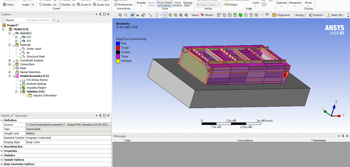
In photo below, you can see ship structure with water domain, upto level of ship draft 1,2 meter.
Ship structure made of shell elements & water with solid elements.
I don't see Fluid Solid Interface under Model Tree. why?
Do i need fluid domain which contain air + water both?...Or water upto ship draft is enough?
March 31, 2022 at 12:11 pmtumulpurwar
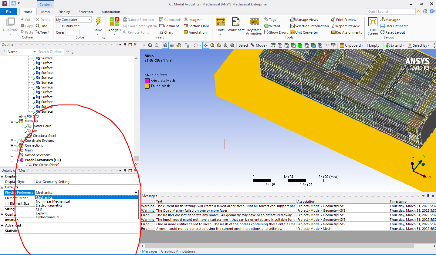
SubscriberAlso Peter..Solid water domain ever failing in mesh, is there is way around where these two elements shell and solid can be meshed calmly together?I already shared them in spaceclaim through workbench tab.
And also want clear out, water domain will be meshed with CFD or Mechanical under "Physics Preference"...See attached photo.
April 1, 2022 at 7:48 amErKo
Ansys Employee
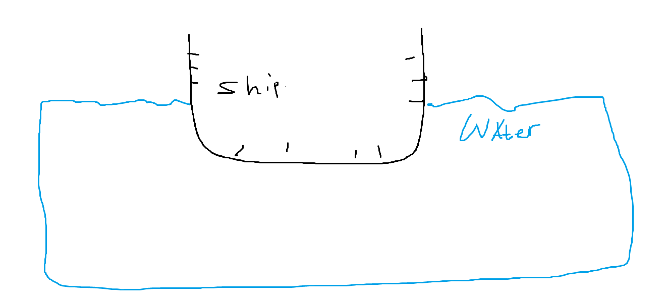
You are not doing CFD analysis so we do not use that setting, just use Mechanical - also the shell structure I suppose is slightly submerged in the water (say due to buoyancy equilibrium, the water line will be higher), and does not just hover on top of the water I suppose - so you need to place and create the water domain as the structure would be floating submerged in the water (simple schematic shown below). Also make the bottom of the "sea/water" a bit deeper as the fluid added mass might be influenced if it is to close to the water sea bottom (typically the fluid added mass increases when the hull is close to the seabed, so e.g., in shallow waters). Finally perhaps Peter can help with the details on trying to mesh this as it can be challenging due to the many faces in the shell structure.
April 1, 2022 at 8:09 amtumulpurwar
SubscriberHi Ekoston
Thanks for replying..In photo , it looks ship is not submerged, but actually it is submerged upto 1,2 meter.
I also wanted know,Its also possible to have waves, instead of calm sea for getting wet modes of ship?I guess wet modes values can change if there are waves instead of calm water in photo above...Will it be possible in Modal Acoustic, or do i will need than FSI?
Thanks
Regards
Tumi
April 1, 2022 at 8:16 amErKo
Ansys Employee
'I also wanted know,Its also possible to have waves, instead of calm sea for getting wet modes of ship?'
The only way to account for that here is by perhaps lowering the ship in the sea so have it a bit more submerged depth, depending on the wave height.
I should say though that I have never seen this (account for waves in fluid added mass) in the global vibration analysis of ships so I do not believe it is accounted for and looked at since it is probably minor (specialists doing these very tricky calculations would not really think about accounting for this as it must be minor - shallow waters on the other hand can change the fluid added mass a lot).
Erik
April 1, 2022 at 10:47 amtumulpurwar
SubscriberHi Eric
Thanks for that idea.
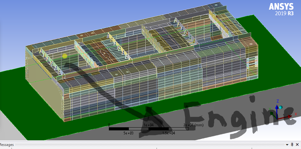
If i want do local analysis due to engine excitation in this structure,(my engine sit on back portion of one end of ship structure) , i have engine excitation(force and moment value from engine manufacturer), just if you can tell in short procedure, do i need do than harmonic response?
One More question, Most of time in Shipbuilding design offices, we dont want to create detailed FEM model say for global analysis, this can lead to reduction in total stiffness of Complete detailed model, offcourse overall weight we can match by increasing density of material...but i dont have idea, how in such case we can match our stiffness(of less detailed FEM model) to total stiffness of complete detailed model?
Thanks
April 1, 2022 at 11:11 amErKo
Ansys EmployeeHi
I can't give anymore details as this is very specific to modelling this type of problems, something I can not provide help with.
What we can say is that we need a harmonic acoustic analysis instead of modal acoustic.
As for the excitation, if you have some values, one can apply them as a rotating remote force (search for rotating force on the internet and in the forum).
Finally have in mind that if we also expect the excitation (e.g., especially at low rpm close to the bending mode resonance of the ship) to excite the whole ship so the global modes (1st bending,...), and not any local modes say around the section that you are modeling, so you need to model the whole ship, and that is going to be very difficult since I do not think this approach can cope with such a large model.
Even more important and challenging is damping that is very important here and will determine the response at the global and local resonances of the ship and that is something we do not and can not account for (acoustic elements).
Fluid Added Damping is the big unknown in this type of modelling which extremely tricky and only specialists undertake, since they also have experience from measurements/see trials often on what the fluid added damping is on the ship.
So I would be very careful to get into this type of modelling as it is too difficult (only as I said specialists can do this well), as we can not account and do not know the damping of this system.
Unfortunately I can not say much more on this subject as I said and I will leave the discussion here from my side.
I hope all my comments in this area give you an idea how challenging this is, and I wish you good luck.
All the best and take care.
Erik
April 1, 2022 at 11:43 amtumulpurwar
SubscriberThank you Eric very clear and fine information provided by you.
I will be doing further these analysis, will post here results once comes.
Thanks
Good day!
April 4, 2022 at 4:17 amtumulpurwar
SubscriberHi Peter
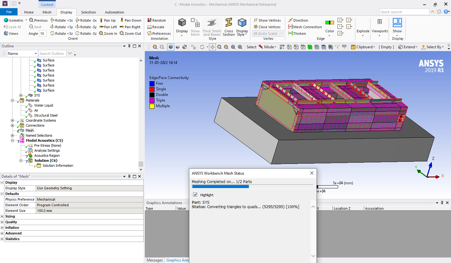
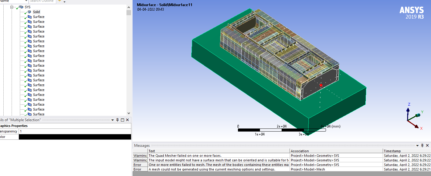
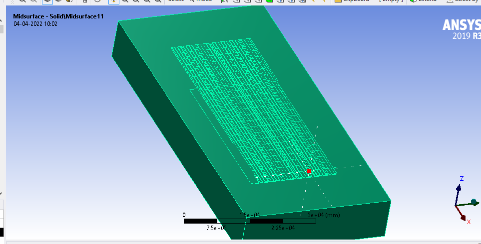
I need help in meshing..my structural shell mesh along with acoustic domain( solid mesh ) fails..mostly the problematic geometry is Acoustic domain(meshed with solid element).
I tried decreasing mesh size of fluid/acoustic domain, by different ways but it always fails.
Can you suggest any idea...thanks
The imprints in 2nd photo , over fluid domain is due to share topology
One of the warning is:
The input model might not have a surface mesh that can be oriented and is suitable for tetrahedral meshing. Please check the input CAD model for errors.
April 7, 2022 at 5:09 amtumulpurwar
SubscriberHi Ekoston
Just one question, do the fluid domain(solid element) and my ship(shell element), will they both will share topology,in spaceclaim or not?
Thanks
Viewing 17 reply threads- The topic ‘Structure – Added Mass Vibration’ is closed to new replies.
Innovation SpaceTrending discussionsTop Contributors-
4728
-
1565
-
1386
-
1242
-
1021
Top Rated Tags© 2026 Copyright ANSYS, Inc. All rights reserved.
Ansys does not support the usage of unauthorized Ansys software. Please visit www.ansys.com to obtain an official distribution.
-


