-
-
May 22, 2024 at 1:47 am
Kishore S
SubscriberHello guys,
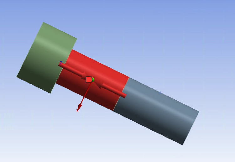
So i am facing a challenge, I am applying bolt pretension on the bolt shown below, i am applying bolt preload of 13750 N on the shank body , i have split the the bolt body accordingly , used share in spaceclaim to equivalence the face , made a local coordinate system for the bolts , all the basics,Used bonded contact for thread and thread's mating surface and Frictional contact(U=0.15,Adjust to touch) for bolt head and underlying surface ,It is a M8 bolt , so the average stress F/A is 273 Mpa (For the shank part)but stresses found in the bolt seem to be much Higher like in the range of 1000 MPa, There is no contact for the shank ,there are no other forces , there are some supports far away from the bolt location,only one load step i am applying only bolt pretension, all the bolts in the model are showing stress like 3-5 times the avaerage stress value ,and in another separate model this is the case, there is bending surely ,contour for contact pressure for the contact under bolt head to underlying surface shows one circle divided into two semi circles, more than 100 MPa in one part of the circle with max bein 823 MPa(semi-circle) and less than 5 MPa in the other part of the circle(Semi-circle) and even if i use a translational joint method instead of bolt pretension the results are similar and if i apply bolt pretension as 10 N the stress are still 4-5 time the average stress.
The thing is if i suppress all the other parts and build a solid block surrounding the bolt in spaceclaim with the thread being in contact and the bolt head being in contact with the underlying surface and with the same pretension and pretension settings then the stresses found are matching with the average stress, it doesnt seem to be a modeling mistake of the bolts.
Also in my original model if i split the body of the shank and apply the forces manually as shown below,just for rough comparison i know it is not the way,then the stessses found are atleast in the range of average stress with max stress being 390 MPa unlike bolt pretension which shows about 1000 MPa.
Also,
1) In bolt pretension details, i have only chenged define by to load and entered the 13750 N value rest all is default and program controlled
2) I cannot share the model or screenshots of the model other than the bolt pics i have shared above,sorry .
3) all the stresses mentioned above are Equivalent(Von Mises)Stress.
So My question is simple what all could make stresses show 4-5 times the average stress of bolt pretension force no matter how small(10 N)or big the force is when the same bolt matches with average stress when built a solid block around it under similar conditions and is in the range when i apply force manuallyin the original model when there are no other forces and the supports are pretty far away from Bolt location.Please give me ideas where it could have gone wrong,also the total deformation in the original model just for the 1 bolt- Max defromation=0.84 mm seems fine.
-
May 23, 2024 at 1:44 am
peteroznewman
SubscriberI expect the bolt head is bending relative to the threads due to the flexibility of the structure you have hidden. Bending stresses will add to the tensile stresses that you expect to see from the bolt pretension.
Plot the directional deformation on just the flat bolt head using the Coordinate axis along the bolt axis to get an estimate of the tilting of the head relative to ground. Do the same for the flat face at the thread end of the shank to see how much that face is tilting relative to ground. The difference between those two plots is the bending of the head relative to the threads.
-
- The topic ‘Stresses Found in bolt not in the range of Hand calculation average stress’ is closed to new replies.


- LPBF Simulation of dissimilar materials in ANSYS mechanical (Thermal Transient)
- Simulate a fan on the end of shaft
- Nonlinear load cases combinations
- Real Life Example of a non-symmetric eigenvalue problem
- How can the results of Pressures and Motions for all elements be obtained?
- Contact stiffness too big
- Test post on Forum – LLM response – SC
- 13-Node Pyramid Element Shape Function
- Element Birth and Death
- Python-Script to Export all Children of a Solution Tree

-
4492
-
1494
-
1376
-
1209
-
1021

© 2025 Copyright ANSYS, Inc. All rights reserved.


