General Mechanical

General Mechanical

Topics related to Mechanical Enterprise, Motion, Additive Print and more.

Stress distribution on hole surface – revolute connector

    • eibanez
      Subscriber

      Hi all,

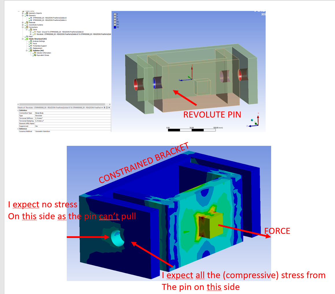
      when running a basic analysis on a bolted connection based on 2 C shaped brackets (one fixed and one pulled away by applying a force on it) I realized that the revolute joint works as if the virtual pin was "glued" along the whole circumference: hence half of the virtual pin causes tension on one side of the hole and the other side causes compression. In reality, the pin surface cannot pull along the surface of the hole, it can only push and compress so the actual stress distribution to be expected I believe is one side totally unloaded (as a matter of fact a small gap will be created) and the other half circumference will see pure compression.

      What settings should be applied to the revolute pin to allow only for compression on the nodes?

      I know one solution would be to split the hole surface into two but that would require to know in advance the direction of the resultant force which is easy in this simple example but much more complicated in some types of joints I need to analyze


      Attached image as explanation Thanks a lot in advance

      Emiliano


    • peteroznewman
      Subscriber

      Delete the revolute joints.  Add a 3D solid model of the pin and use Frictional contact of the pin to the hole. That will correctly apply compression force on the side of each hole as the force is applied and the pin will pull away from the hole on the opposite side. The pin will also exhibit some bending.

    • eibanez
      Subscriber

      Thank you Peter, really appreciated. Does the physical pin need to modeled with zero gap in respect to the hole all it will work even with a small play (which will always be there in the real world)?


      Regards

      Emiliano


    • peteroznewman
      Subscriber

      In older versions of Ansys, you would have to go into the CAD system and put the pin on the left side of one hole and the right side of the other hole to get the clearance taken up in the correct direction before starting the solution.  Newer versions of Ansys include a Stabilization Damping Factor in the Contact definition that allows a pin with clearance to the hole to sit in the center of the hole, not touching any side, and the stabilization will allow the solver to close the gap during the solution, which is an amazing time saver over the older version.

Viewing 3 reply threads
  • The topic ‘Stress distribution on hole surface – revolute connector’ is closed to new replies.