-
-
July 5, 2021 at 3:01 pm
abs95
SubscriberHello,
Does the static temperature at a solid-fluid interface wall give the temperature of the solid? Or should I go with the wall temperature to get the solid temperature? Does the adjacent cell zone play a role in this, as Fluent assigns two walls at the interface: one with a adjacent cell zone of fluid and one with adjacent cell zone of solid?
Thanks!
July 5, 2021 at 3:40 pmRob
Forum ModeratorIt'll give the temperature of the facet, which will be a function of the fluid and solid cell temperatures assuming you've not changed anything on the wall. Wall and wall:shadow are there to give labels to the two sides of the same surface. They're used to allow different roughness settings (for example) on either side.
July 6, 2021 at 8:43 amabs95
SubscriberThank you for your answer. I have this geometry below. I am using this geometry to test my BCs, which I am planning to intruduce to a much more complex geometry. That is why I am also modelling the solid part. For this geometry I have the BCs below.

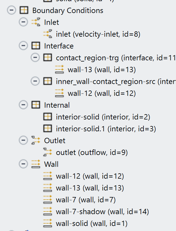 I think I get 4 wall conditions to the interface. 2 (wall 12 and wall 13) are assigned to the interface BC extra to the wall 7 and wall 7 shadow. What do all of these walls mean and why are there 4 instead of 2?
July 6, 2021 at 9:08 amAmine Ben Hadj Ali
Ansys EmployeeInterface will create overlapping and overlapping boundaries. The overlapping part are the wall and its shadow. The other ones are related to the non-overlapping. Check the documentation and in Fluent click on the interface in the Mesh Interfaces and hit "list" to list all information / boundaries related to the mesh interface!
July 7, 2021 at 11:30 amabs95
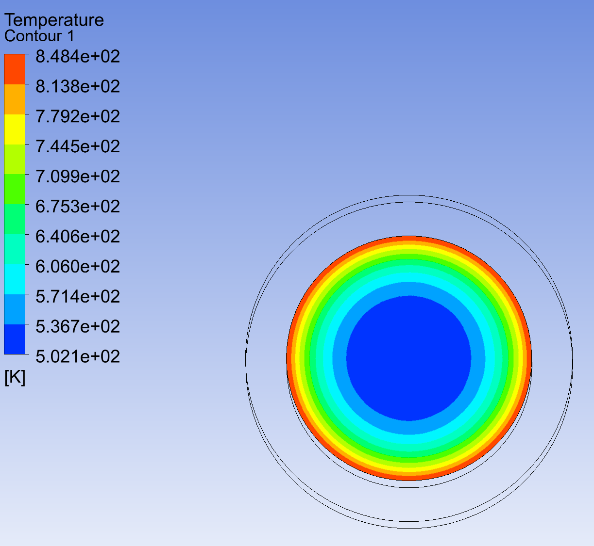
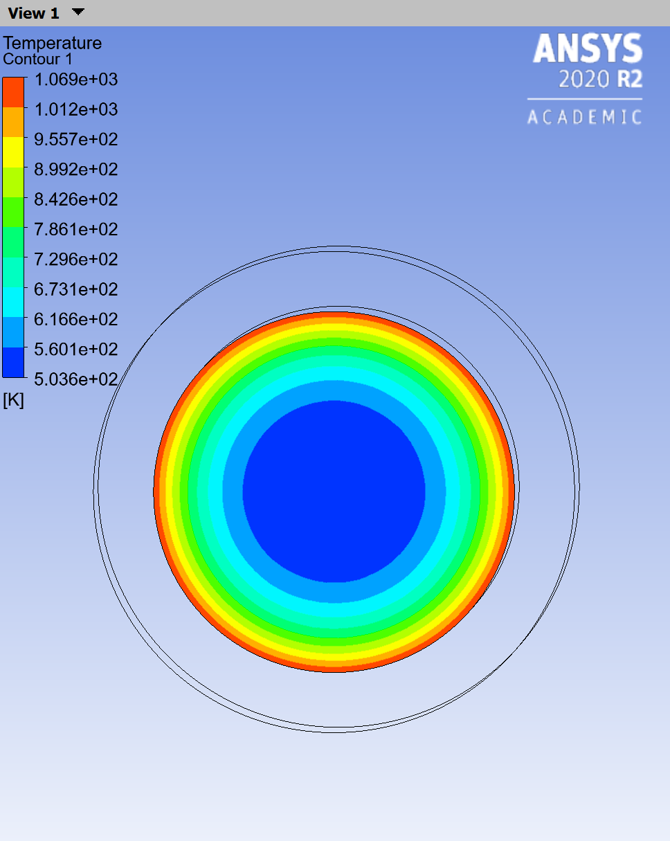
SubscriberIf I I make the solid and fluid one part in the Design Modeler, I dont have the "interface" (contact region src and contact region trg) and their corresponding walls (wall 12 and wall 13) anymore. In that case I am left with only wall 7 and wall 7 shadow. I wanted to see if these two cases (Case 1: With the "interface" and Case2: without "interface") are equvialent. In the both cases I introduced a heat generation rate of 600000 W/m3 and a wall thickness of 0.001 m to wall 7 (also automatically to wall 7 shadow because they are coupled ). Inlet velocity is 0.02 m/s and temperature of 500K. Outer Walls are all adiabatic. In the case 1 I left wall 12 and 13 as default which is heatflux, thickness and heat generation rate 0. Both cases gave me different results. Below are the temperature contours at the outlet for both cases:
Case1:
 Case 2:
My questions are:
1) Why there is a difference of around 200K? Why are the solutions not identical?
2) Which solution can I trust? Which approach is more "legit" ?
3)How can I make the two cases give the same output?
July 7, 2021 at 12:14 pmAmine Ben Hadj Ali
Ansys EmployeeIf you have multibody part you won't have contact or interfaces.
Difference might be due to wrong setup and the definition of walls at the interface. For that reason I asked for mesh interface panel and what Fluent prints if you list that interface.
July 7, 2021 at 2:03 pmabs95
SubscriberI printed the mesh interface before and after initilization. After initilization it tells me one side is "filled" with wall 7 and the other side with wall 7 ratio. Does that mean the solution without walls 12 and 13 is more correct and I should get rid of them by deleting the mesh interface (contact region)?
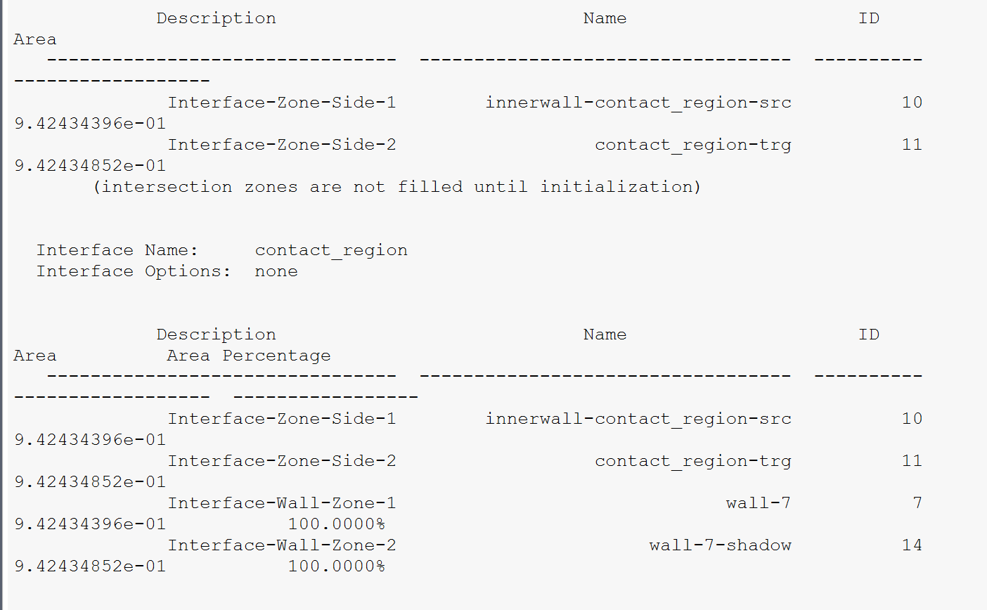 Edit: I found out that by deleting the mesh interface I get rid of also the wall 7 and wall 7 shadow. Should I in that case check the "Matching" option at the "Interface Options" ?
July 7, 2021 at 7:18 pmAmine Ben Hadj Ali
Ansys EmployeeMatching is not for walls. Rather use the option coupled. But any way the sides are matching. Do both cases converge well? What about the heat flux report at the interfaces and other boundaries?
July 8, 2021 at 8:08 amabs95
SubscriberAfter rerunning it, I realized I posted something wrong for the outlet Temperature for the case 1. Instead of having lower temperatures I have higher temperatures:
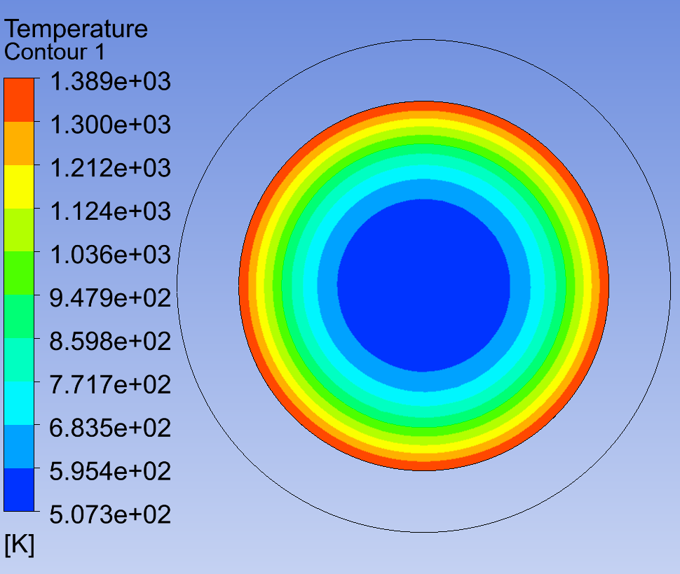 Both cases converge well (continuity, x, y, z velocities, k, omega below 1e-3 energy below 1e-6 )
For the case 1: I have 0 wall heat flux at all boundaries (including interfaces), which makes sense to me as I set the heat flux on the lateral outer boundary and the outer and the outer "ring walls" next to the inlet and outlet equal to 0.
However for case 2 (screenshots below): I have non zero heatflux at the rings and therefore (I think) non-zero heat flux at the interface.
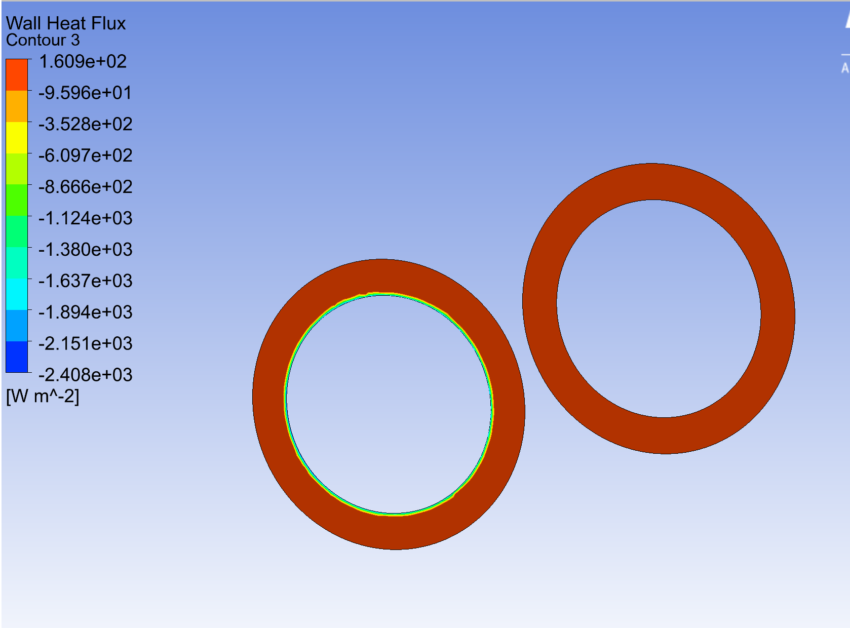
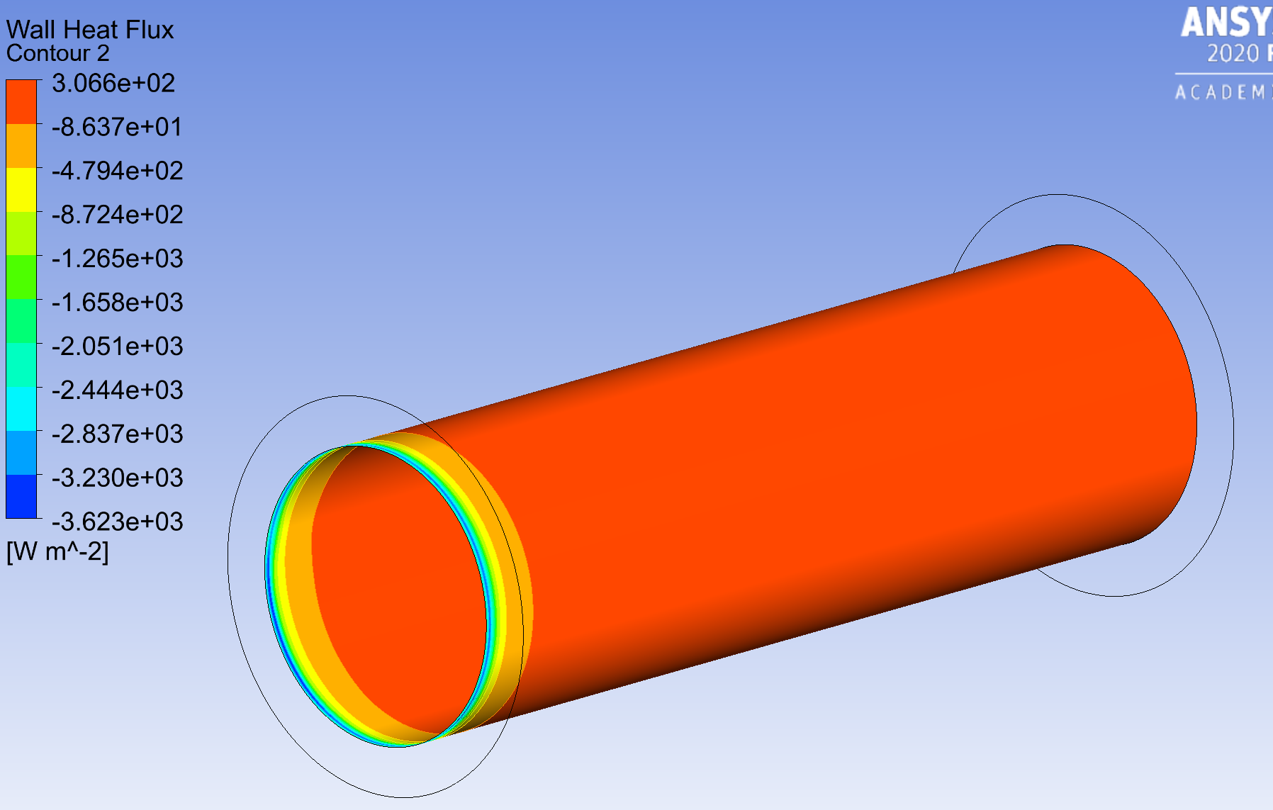 It appears that Fluent did not calculate the equations with rings being adiabatic, although I set the heat flux 0 there as a boundary condition. Why would Fluent in the case 1 implement my boundary condition how I set it and not for the case 2?
July 8, 2021 at 8:14 amAmine Ben Hadj Ali
Ansys EmployeePlease do the Flux Report in Fluent and not in CFD-Post.
July 8, 2021 at 9:06 amabs95
SubscriberFor the case 1: I have 0 W at the all outer boundary (rings and lateral) and contact region trg and src and wall 12 13, 0.00729 W at wall 7 , 565.453 W at the wall 7:shadow
For the case 2: again 0 W at the all outer boundary (rings and lateral), 161.860 W at wall 7, 403.605 W at wall 7 shadow
July 8, 2021 at 11:18 amAmine Ben Hadj Ali
Ansys EmployeeBoth cases showing strange behavior. Focus on the case with no interfaces and try to understand why the flux at one side of the wall does not match the flux on the other side of wall.
July 8, 2021 at 4:06 pmabs95
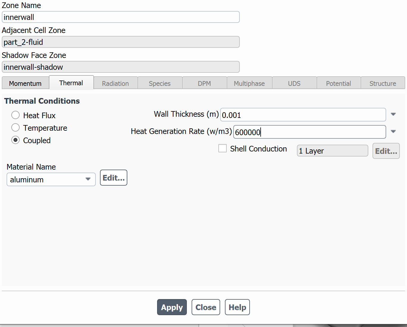
SubscriberCould it be because how I implemented the heat generation rate and the wall thickness? What I am trying to implement in the end is a surface heat source at the wall which will eventually heat up the adjacent solid and fluid. (I know the cases I show does not heat up the solid because I set the outer walls to be adiabatic but eventually I will set a convection BC there after solving these issues) . As setting a surface heat source was not possible, I had to go with the option of putting a small thickness and giving the equivalent volumetric heat source.
July 9, 2021 at 3:59 pmRob
Forum ModeratorIf the solid is surrounded by adiabatic walls it makes sense that more heat is added to the fluid: it's going to be cooler. If you check the heat you add into the wall against the inlet & outlet how does it tie up?
July 9, 2021 at 4:05 pmAmine Ben Hadj Ali
Ansys EmployeeYou then should get the net impact of that as you know the thickness and the area of the walls.
July 12, 2021 at 7:55 amabs95
SubscriberWhat do you mean with heat added into the wall against the inlet & outlet? How do I check it?
Yes the heat added by the source is 565.488 W. The net heat between the walls for the cases 1 and 2 are 565.461 W and 565.4656 W respectively, which are almost the same as the original inputted heat source. Why would however heat fluxes at the walls be different for two cases?
July 12, 2021 at 10:19 amRob
Forum ModeratorUse the Flux Reports, tag inlet and outlet and look at the difference. That should equal the amount added through the wall.
If you're comparing 565.461 with 565.4656 you're looking at a variation of approximately 0.0001%. Given it's an iterative solver I'd be fairly confident in saying the difference is due to convergence and rounding error. Remember we're dealing with engineering numbers, so don't expect agreement to 19 significant figures.
July 12, 2021 at 10:48 amAmine Ben Hadj Ali
Ansys EmployeeDifference is not high and acceptable.
July 12, 2021 at 11:08 amabs95
SubscriberWith the different heat fluxes at the walls I actually meant this:
For the case 1 with the "interfaces" the wall and wall shadow have 0.00729 W and 565.453 W respectively.
For the case 2 without the "interfaces" the wall and wall shadow have 161.860 W and 403.605W respectively.
My question was actually: Although the net heat at the wall and wall shadow is the same for both cases why are the individual fluxes at the wall and wall shadow very different between two cases? Sorry I should have formulated my question more clearly.
The net heat through inlet and outlet for case 1 and case 2 is -456.2869 W and -246.943 W respectively, so they are no equal to the heat added through the wall.
July 12, 2021 at 11:18 amAmine Ben Hadj Ali
Ansys EmployeeOkay: that is weird and for that reason I was asking how you defined the interfaces: manually or automatically generated. From your interface screenshots in the top: the interfaces are matching and 100% overlapping. I recommend that you test one run with Coupled Mesh Interface.
July 12, 2021 at 1:13 pmabs95
SubscriberThe interfaces were automatically generated. I ran with "Coupled Walls" option. The results are the same.
July 12, 2021 at 4:04 pmAmine Ben Hadj Ali
Ansys EmployeeIf both cases are converging and monitor points are not varying I am expecting that both result should be same with slight differences assuming now your setup at the interface is correct and all other settings and conditions are same.
What you can do is the following: start from wall wall shado cars (no nci) slit the wall change them to interfaces and create a new interface connection and run.
July 13, 2021 at 12:46 pmRob
Forum ModeratorFor info, the slit command is in the TUI under mesh/modify-zones
August 9, 2021 at 1:56 pmabs95
SubscriberIt worked out, they match if I do like that! Thank you very much!
Viewing 23 reply threads- The topic ‘Static Temperature equal to Wall Temperature?’ is closed to new replies.
Innovation SpaceTrending discussionsTop Contributors-
4708
-
1565
-
1386
-
1242
-
1021
Top Rated Tags© 2026 Copyright ANSYS, Inc. All rights reserved.
Ansys does not support the usage of unauthorized Ansys software. Please visit www.ansys.com to obtain an official distribution.
-


Ansys Assistant

Welcome to Ansys Assistant!
An AI-based virtual assistant for active Ansys Academic Customers. Please login using your university issued email address.
Hey there, you are quite inquisitive! You have hit your hourly question limit. Please retry after '10' minutes. For questions, please reach out to ansyslearn@ansys.com.
RETRY


