Ansys Assistant will be unavailable on the Learning Forum starting January 30. An upgraded version is coming soon. We apologize for any inconvenience and appreciate your patience. Stay tuned for updates.
General Mechanical

General Mechanical

Topics related to Mechanical Enterprise, Motion, Additive Print and more.

Static Structural Connections

    • tonyweeks11
      Subscriber

      Currently have a two piece model.

      1. Base "table" piece that is rigid and has been modeled as such

      2. Bracket piece that is attached to the base structure and is to be assed for forces and how it reacts/stress

      Current have contact surfaces as shown in images below between the hooks on the bracket which connect to the studs on the table as no separation as well as the bottom side of the bracket and the top surface of the table. This is the only way I can get a solution to solve without have a convergence issue. Also note the force which is on the bracket top surface and parallel to that surface. How should I model these contact surfaces?

    • peteroznewman
      Subscriber

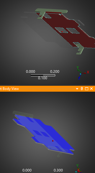
      Frictional contact between parts is the most realistic contact definition but requires some effort to get convergence. You can trade off some realism to make convergence easier such as using No Separation and a Rigid body.

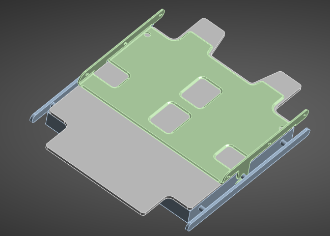
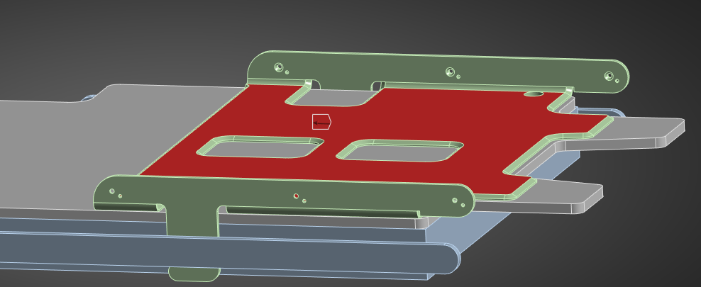
      While you might get this model to converge with the parts already in the assembled state, it seems like an assembly motion is required to get the bracket into the assembled state. The green bracket has two tabs that reach down on each side of the table. 

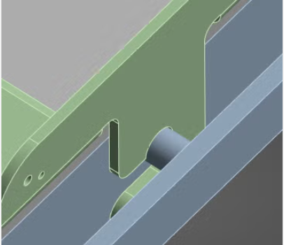
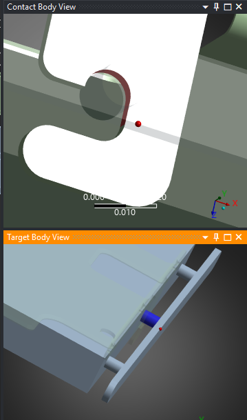
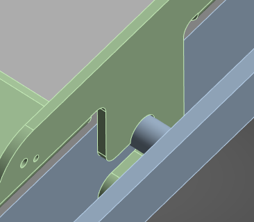
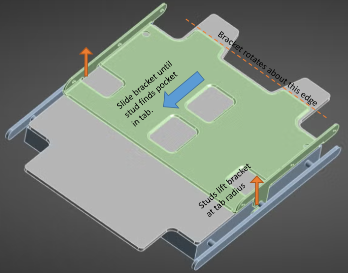
      I can imagine the assembly sequence is to drop the bracket down onto the large surface of the table half a tab width along the +X direction so that the now white tab has its radiused corner tangent to the stud, then slide the bracket along the -X direction. This causes the bracket to lift up over the stud until it drops back down around the stud.

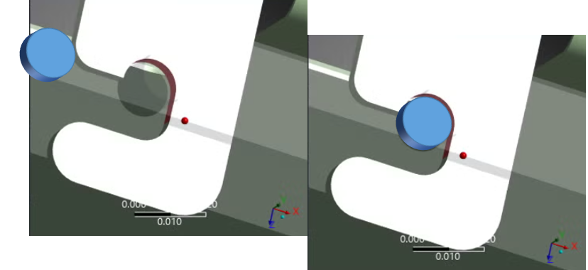
      During assembly, as the contact between the radiused corner and the stud lifts the tabs up, the bracket would probably rotate around the two flanges that stick out the back.

      When is the force on the top of the bracket applied?  Is it there during assembly or only after?

      What exactly are the loads that you are trying to simulate?

      • tonyweeks11
        Subscriber

        see below


    • tonyweeks11
      Subscriber

      The force on the top of the bracket is applied only after assembly. The force on the top of the bracket is simulating a load where this bracket along with the table will withstanding weight on top of the bracket at an angle (the underlying table rotates). I have calculated forces to load the bracket in these use conditions. In reality there will be the force I added along with a perpendicular force which I have ignored for simplicity as the force perependicular to the bracket should be absorbed by the body and underlying table but maybe I should model this as well. 

    • peteroznewman
      Subscriber

      What do you mean the weight on top of the bracket at an angle?

      Model reality. There is no reason to ignore the perpendicular force. The bracket has to transfer that force to the table at the contact faces.  If you don't include that force, it can't cause any stress in the bracket.

Viewing 3 reply threads
  • You must be logged in to reply to this topic.
[bingo_chatbox]