-
-
December 25, 2019 at 1:35 pm
-
December 25, 2019 at 5:45 pm
peteroznewman
SubscriberDo you know how to create a Named Selection so you can find Node 2130 referred to in the Error message? That way, you can get near the source of the problem.
Use File, Archive to save a .wbpz file to attach to your reply if you want me to look at it more closely.
-
December 26, 2019 at 10:33 am
shisha3301
SubscriberThanks very much the file is attached as a zip with the project files and wb file in a folder, in the workbench model there are many standalone projects in the same page so the project is the last one at the bottom.
-
December 26, 2019 at 1:12 pm
peteroznewman
Subscriber
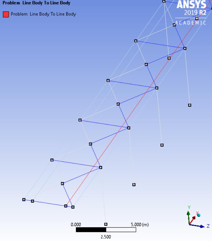
The model has Bonded contact of 1 red edge to 61 blue edges.Â
I don't know why, but that bond is causing a problem, while the same one on the other side does not.
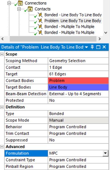
The fix is to change the Formulation of that Bonded contact to MPC.
Then, after a Solution, you can click on the Solution Information folder and then click on the Graphics tab to see the CE elements on the display that shows which nodes were tied together by the Bonded contact as shown below by the little red lines. The mesh size shown is 500 mm.
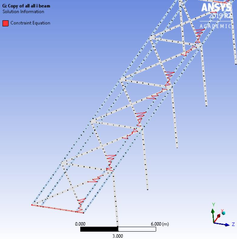
Is that how you want that long beam tied to the diagonals?
If not, you will have to chop all the beams up into many small pieces so end points are connected.
If this answers your question, please mark it with Is Solution or ask a followup question.
-
December 26, 2019 at 3:44 pm
shisha3301
SubscriberThanks very much the solution you suggested has helped me but further more reduction in element size gives an error, so I was wondering if you can suggest how I can chop the beams into small pieces as I tried doing that in design modeler but they ain't in same sketch.
-
December 26, 2019 at 4:02 pm
peteroznewman
SubscriberOpen the Geometry in SpaceClaim, go to the Workbench tab and see if the Share button does a better job.
Otherwise, it will be a lot of work in DesignModeler making new sketches, or using the Split Edge function.
-
December 26, 2019 at 5:40 pm
shisha3301
SubscriberThanks very much mr. Peter for your help as the share option helped me alot but I have a final question if that's fine with you, how can I insert a load at a specific point along beam .
-
December 26, 2019 at 6:09 pm
peteroznewman
SubscriberIt is best to open the Geometry and split the beam at that specific point so there is a vertex to select in Mechanical.
-
- The topic ‘STATIC STRUCTURAL’ is closed to new replies.
- LPBF Simulation of dissimilar materials in ANSYS mechanical (Thermal Transient)
- Real Life Example of a non-symmetric eigenvalue problem
- How can the results of Pressures and Motions for all elements be obtained?
- Contact stiffness too big
- Element Birth and Death
- Python-Script to Export all Children of a Solution Tree
- Which equations and in what form are valid for defining excitations?
-
4592
-
1494
-
1386
-
1209
-
1021
© 2025 Copyright ANSYS, Inc. All rights reserved.


