-
-
January 26, 2020 at 2:24 pm
tahm
SubscriberIs it possible to model and analyze simple spring system using ANSYS Workbench? -
January 26, 2020 at 6:14 pm
peteroznewman
SubscriberYes.
-
January 26, 2020 at 8:44 pm
tahm
SubscriberCould you please explain how? -
January 26, 2020 at 8:46 pm
tahm
SubscriberIf you need a spring system in series and force applied on nodes? -
January 27, 2020 at 12:03 am
peteroznewman
SubscriberI would do that in a spreadsheet using springs in series formula.
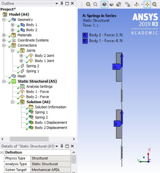
That would take a lot less time than building the model shown below.
The ANSYS 2019 R3 archive is attached.
If this answers your question, mark the post with Is Solution to mark the Discussion as Solved, or ask a followup question.
-
January 30, 2020 at 9:49 am
tahm
SubscriberCan't we just create nodes and connect it with spring elements as we do in APDL?
I am not able to open the file as the version I am using is ANSYS 19.1
-
January 30, 2020 at 1:24 pm
peteroznewman
SubscriberYes, you can write a few lines of APDL to create two nodes, two springs, displacements, a load and you are done, but you asked about Workbench.
Like most software, older versions are unable to open the files saved in newer versions.
-
January 30, 2020 at 1:38 pm
tahm
SubscriberYes, I wanted to know if it can be done easily using workbench.
The picture above shows 2 surface bodies instead of nodes, that's why I asked. -
January 30, 2020 at 1:48 pm
peteroznewman
SubscriberIt depends on your definition of easily. The Workbench model is easily made because it requires no knowledge of APDL. Maybe there are simpler models in Workbench that just use nodes, but the typical Workbench user doesn't usually need to use them.
If you know APDL, then it would be easier to use that than Workbench.
If you just want an answer to a simple spring system, then you don't use ANSYS at all!
-
January 30, 2020 at 2:38 pm
tahm
SubscriberTrue. -
September 25, 2023 at 9:58 pm
Abbas Kadhir Ali Mohamed Abbas
SubscriberHi Peter,
I do not see any attached archive file.
I have a similar 2D axisymmetric model where I have a contact spring setup and wanted to understand the dynamics of a part under force. I also wanted to do a parametric study with different stiffness values and their effect on the dynamics of the part. But when I plotted the deformation of the part under various stiffnesses ranging from 200 N/mm to 500 N/mm, all the deformations were exactly the same.
I did a similar sensitive study with ranging preloads which worked but changing stiffnesses did not work. Does anyone know the reasoning and solution?
P.S. I tried setting up the Spring contacts in the respective coordinate system of contacts rather than Global. Did not work either.
keenly awaiting your suggestions -
September 26, 2023 at 9:40 am
ErKo
Ansys EmployeeHi
I would suggest to open up a new post as this one is very old.
Closing this post.
Erik
-
- The topic ‘Spring system’ is closed to new replies.


-
4934
-
1638
-
1386
-
1242
-
1021

© 2026 Copyright ANSYS, Inc. All rights reserved.


