-
-
June 10, 2023 at 12:16 am
xiao
SubscriberHi Community,
I have a problem defining a boundary condition that is not fixed or pinned. Instead, I want to assign a stiffness to the node. As shown in the figure below.
In this figure, the rotational boundary condition is free. But the translation boundary condition is provided by a stiffness value.
When I start doing this job, I think I could assign a spring aligned to the directions, which are not fixed. For example at point A, the vertical direction is fixed. At the same time, the x and z directions are semi-rigid. I thought I could create a line element and then change the element type to combin14 (which is a spring). But I don't know how to do it. Is it possible to change the element type to combin14? Or, is there any other way to define these flexible boundary conditions?
The second figure shows how other people do it (only for visualization, the model is not provided).
Â
Thanks,
Xiao
-
June 12, 2023 at 2:10 pm
Lydia
Ansys EmployeeDear Xiao,
I think that you can directly insert a spring object (through connections object) and select it body-ground. You propably don't need to create a line element, you can do it directly.
Another thing you could try is to add a bushing joint, also through the connections object.Â
I hope this helps,
Lydia
-
June 14, 2023 at 2:39 am
xiao
SubscriberHi,
Thanks for the reply. I will try the the first suggestion you mentioned. And will let you know how it works.
Â
Thanks,
Xiao
-
-
June 12, 2023 at 4:52 pm
Bill Bulat
Ansys EmployeeHi Xiao,
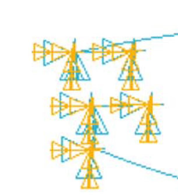
Your second figure appears to have been made by the MAPDL solver, not in Mechanical. Are you by any chance modeling directly in the MAPDL environment, or are you instead using Mechanical (presumably with APDL command objects)?
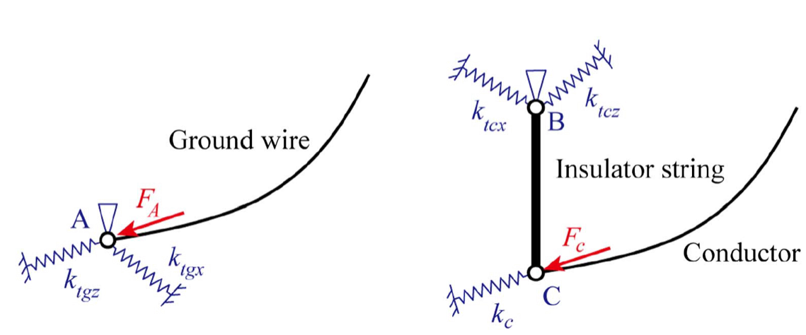
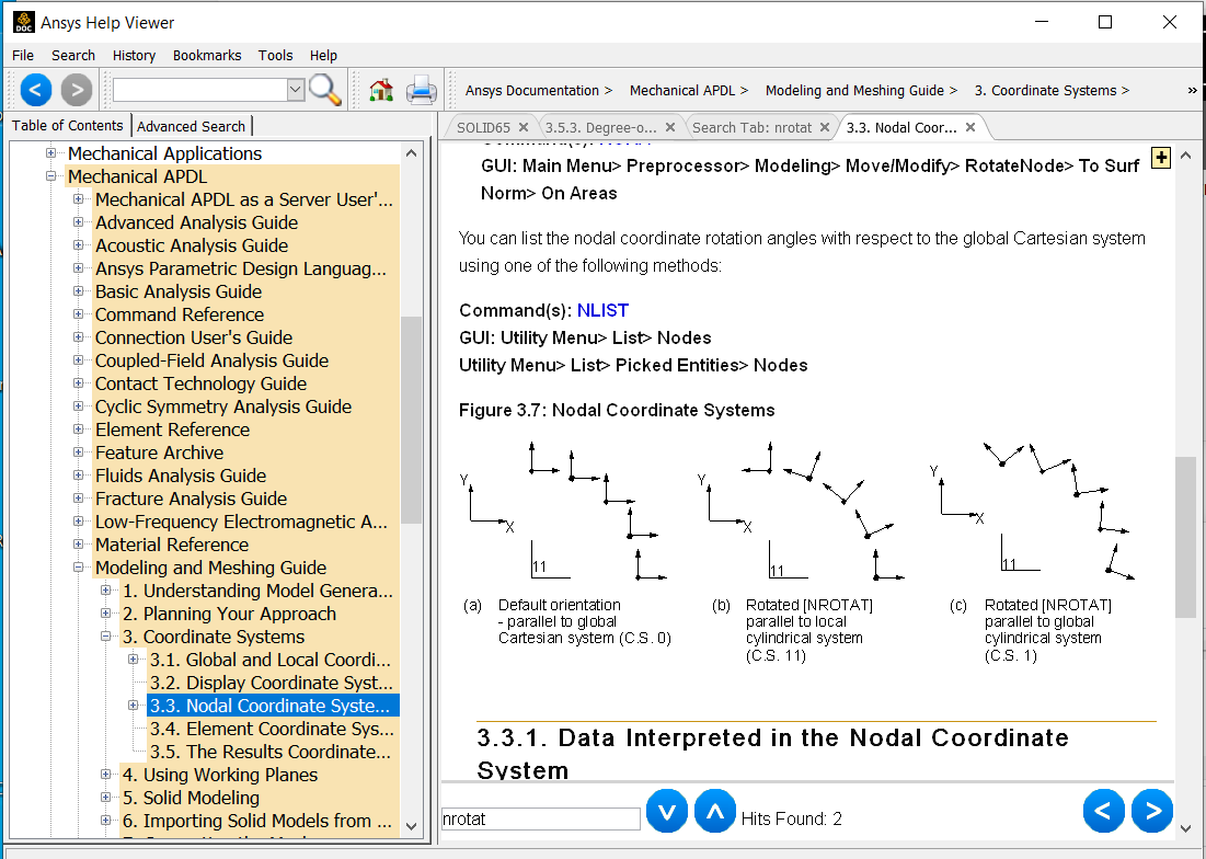
Your first figure suggests to me that your objective is to only allow motion parallel to the ends of electric conductors, and that the end is not necessarily aligned with/parallel to any of the global Cartesian directions. The nodal directions may be modified, so that nodal UX, UY, & UZ directions are aligned with some other "local" user-defined coordinate system that you create. This can probably done with a button somewhere in the Mechanical GUI. I find it simpler to use a command object with the NROTAT command (consider locating/reviewing the Help articles shown in the images below):
Â
Â
You can constrain motion in directions normal to the electric conductors with the D command.
Â
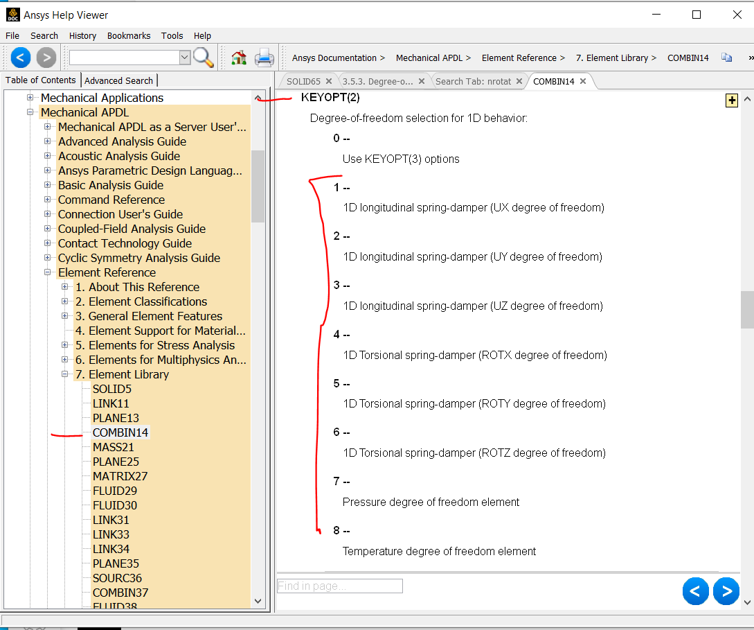
When Mechanical is used to create springs, I'm pretty sure that they are modeled with COMBIN14 (the 3D spring option with 3 DOFS - UX, UY, and UZ - at each end node). A command object can be used to convert them to a single DOF spring (UX, UY, or UZ) if desired by setting the value of KEYOPT2 with the KEYOPT command:
Kind regards,
Bill
-
June 14, 2023 at 2:42 am
xiao
SubscriberHi Bill,
Sorry for the late reply. The spring should aligned with the global x,y,z direction. But I will try what you mentioned.
I will try what you have suggested and keep you posted.
Â
Thanks,
Xiao
-
-
- The topic ‘Spring Boundary Conditions’ is closed to new replies.
-
3462
-
1057
-
1051
-
918
-
896
© 2025 Copyright ANSYS, Inc. All rights reserved.