-
-
April 3, 2019 at 3:07 pm
hassam
Subscriber -
April 3, 2019 at 3:14 pm
peteroznewman
SubscriberA spiral is not axisymmetric. If you want to solve for how the cold fluid heats up as it spirals through the solid, then you will need a 3D model.
Note that in Mechanical Steady State Thermal, you can have a line body element that carries "fluid" and potentially solve this problem without resorting to CFD if you can come up with a convective heat transfer coefficient.
-
April 3, 2019 at 3:39 pm
hassam
SubscriberI want to make this spiral structure also to see the stress concentration areas when high pressure is applied within the cylinder. Would it be ok if i just create hole on the out cylinder. This will represent a ring on the cylinder. I can use this to evaluate stresses and for the heat dissipation i can use line body element as you suggested. I know the cooling liquid is glycol so I know the specific heat capacity of fluid. this is not a CFD analysis. The spiral structure is only for steady state heat analysis (Heat Dissipation)
-
April 3, 2019 at 7:54 pm
peteroznewman
SubscriberI would say a hole in the 2D that makes a ring in the cylinder is a good approximation to evaluate the stress in the cylinder. It is a half a circle in each half that when assembled makes a circle, right?
-
April 4, 2019 at 2:28 pm
hassam
SubscriberThank you Peter for your response. It is actually a rectangle which is shown above in 2D. When rotated around centre axis it makes a composite cylinder. So if I make a hole in the outer cylinder. It will be axisymmetrical rotated to form an empty ring within the cylinder. In Real life it will be achieved by 3D printing the outer cylinder.
Peter can you please guide me through the steps to perform a heat analysis. How to create a spiral body element on the outer cylinder to perform heat dissipation analysis. ?
-
April 4, 2019 at 9:16 pm
peteroznewman
SubscriberPlease make a sketch and write down all the known boundary conditions and material properties. Insert an image of that sketch into your reply. Let's do the 2D model first.
-
April 8, 2019 at 4:45 pm
-
April 9, 2019 at 4:41 pm
peteroznewman
SubscriberYou need a couple more BCs.
The outside face of the cylinder, is that convective cooling to the air? What is the convective heat transfer coefficient? What is the air temperature?
Since this is a learning model, let's assume the temperature on the two circles representing the cooling fluid are 20 C at the fluid inlet and 100 C at the fluid outlet. I just made up that last temperature. When you build the 3D model, you will solve for this temperature, but for this 2D learning model, we will specify it. When you do the 3D model, you will need the convective heat transfer coefficient of the fluid to the spiral wall.
If you wanted to put in a three more holes between A and B, you could set the temperature of those holes at 40, 60 and 80 C.
-
April 14, 2019 at 1:22 pm
hassam
SubscriberHello peter sorry for late response.
I was unable to find convective heat transfer coefficient and was told to assume a value for the worst case scenario. '
The outside face of cylinder is room temperature and convective cooling to air.(atmosphere)
Air temperature is 22 degree C
The inlet temperature of fluid is 20 degree C
i know the diameter of spiral and length also pitch.
Â
In the mean time I have attached the model picture with the circles I draw on the 2D model and need to create an empty space. Which tool i should use which will remove material in the circles.
Â
Â
-
April 14, 2019 at 3:00 pm
peteroznewman
SubscriberThere are several ways of making hole, but you can also just imprint the face with the circular edge and assign the temperature to the circular face.
Try Extrude with the option to Cut Material.
-
April 15, 2019 at 12:49 pm
hassam
SubscriberThanks Peter.
I cut and extrude and here are the Von misces stress results which doesnot show much of difference but looks promising.
Â
I hope its a good approximation of spiral structure.
Regarding thermal analysis I have applied all the boundary conditions. I need to keep the inside liquid temperature in between 20 -120 centigrade.
I think to find the convective heat coefficient i have to go for a 3-D model. Temperature assigned on each hole are rough guesses. I need to work out the actual heat which this coolant is capable of carrying to make sure that inside liquid temperature remains in the range.
Â
Â
-
April 15, 2019 at 3:17 pm
peteroznewman
SubscriberLooks good. You could have left the inside wall as a Temperature BC of 200 C.
How does the temperature distribution look?
Yes, you will have to build a 3D model with a spiral to get the true fluid temperature in the spiral. -
April 21, 2019 at 8:17 am
hassam
SubscriberHi Peter
Thank you very much for your reply. This is the temperature distribution.
Â
Â
I am working now on 3d model on ansys. I made the model on Creo Pro and tried to import it to ansys but there were errors in the structure. The ansys could not identify two different cylinders and made the as one. It is important because there are two different materials involved with different CTEs. Moreover the spiral structure appears only half in the model and irregularites appear. If there is a way to design such model on Ansys will give much better results?
Â
Â
Thanks
-
April 21, 2019 at 11:00 am
peteroznewman
SubscriberSpaceClaim can construct a helix that you can subtract from the cylinder. Create a New Component to keep the two cylinders from uniting, or use the No Merge option in a single component.
-
April 25, 2019 at 12:31 pm
hassam
SubscriberThank you Peter for your response. I have constructed a helix and used cut command to remove the material from the model. The mesh is generated and attached here. I am not sure if this mesh will generate adequate results.
What would be the next steps to find out the value of convective heat transfer coefficient of fluid running through the helical. Should i convert it to line body as suggested in your response! The analysis is performed in steady state thermal.
-
April 25, 2019 at 9:08 pm
peteroznewman
SubscriberYes, you need a line body to mesh with the elements that can simulate a fluid to carry out heat transfer with a specified mass flow rate.
Look in the literature to find a convective heat transfer coefficient for a fluid flowing in a tube.
-
April 27, 2019 at 12:12 pm
hassam
SubscriberThank you for your response Peter.
I have extracted a beam on ansys using the extract beam command. The results are displayed as shown
Â
When i move it to the mechanical only half of the model is displayed. Because I may have applied section view. Moreover what material assignment should be applied to beam since it is just an empty space where cooling liquid will be passing thorough?
Â
i watched tutorial but most of them are doing this analysis on CFD Ansys. What should be the best possible procedure?
-
April 28, 2019 at 2:45 am
peteroznewman
SubscriberIt was a long time ago that I did this model. I will have to find the files for that and take another look.
I think you override the Beam element and define that mesh with a FLUID116 element by using a Command Object under the Line Body.
Read the ANSYS Help on that element by pasting the URL below into the ANSYS Help window that you must first open.
https://ansyshelp.ansys.com/account/secured?returnurl=/Views/Secured/corp/v192/ans_elem/Hlp_E_FLUID116.html?q=fluid
-
May 1, 2019 at 10:07 pm
hassam
SubscriberHi
Thankyou peter for your response. I have given the Model type is as thermal fluid in definition. Its still asking for the material type. It would be much help if you could elaborate the statement
" override the Beam element and define that mesh with a FLUID116 element by using a Command Object under the Line Body"
Â
-
May 2, 2019 at 12:48 am
peteroznewman
SubscriberThis discussion has an example of overriding a beam with an element type LINK180. You use same method, putting a Command object under the Line body, but instead of et, matid,link180 you would use et, matid,fluid116 and then on the following lines would add any other commands needed to define the properties of that element.
-
May 7, 2019 at 4:23 pm
hassam
Subscriber Hello Peter
There is a problem with the model. When I try to run it it gives a limitations error because i am using a student version. I have tried to make a command file but I dont know if its correct since i am not familar with APDL codes
the data which needs to be transmitted through this command file isÂ
Fluid116
Density= 1000kg/m3
Inlet Velocity= 1kg/s
Inlet temperature=20 C
I dont know about the convective heat transfer coefficient. i can assume the worst case scenario.Â
I need to know how to define the inlet mass flow though APDL coding
and how to assign the convective heat transfer coefficient say 50 W/mm2C
I have attached the model for you to see. Please take a look at the command file in the model.Â
-
May 10, 2019 at 3:22 am
-
May 17, 2019 at 1:49 pm
hassam
SubscriberThank you Peter for sharing the model. It was a great help.
-
- The topic ‘
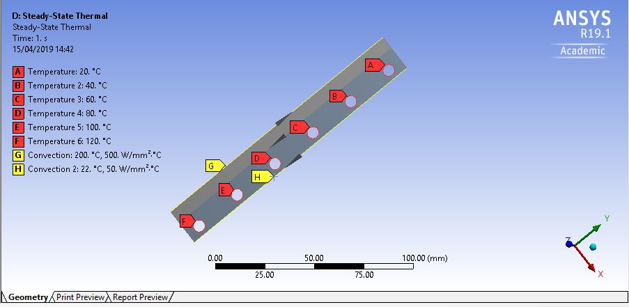
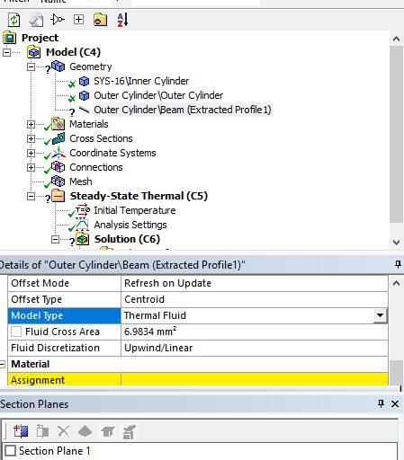
Spiral structure on a 2D axisymmetric cylinder’ is closed to new replies.
- Project lines/edges into a face with the direction normal to the face
- No preview in explorer with scdox file
- Add-in Error Excel
- Fileformats
- Discovery 2025r2 failed to initialize
- Spaceclaim problem
- Using SpaceClaim scripts vs recorded blocks for parametric optimization workflow
- Different Body Naming and Extra Surfaces after Importing Solid Edge Part
- racing royals
- New Computer
-
4597
-
1495
-
1386
-
1209
-
1021
© 2025 Copyright ANSYS, Inc. All rights reserved.


