-
-
April 1, 2024 at 1:20 pm
Anthony Bowers
SubscriberHi all,
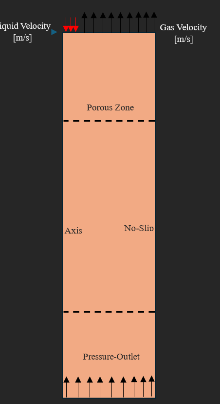
I am simulating a transient counterflow bubble column shown below. My boundary conditions for the respective phase are as follows:
Top:
Liquid( velocity inlet w/ mass fraction of species)
Gas ( velocity inlet w/ negative velocity to flow out side the domain .. species set to zero)
Â
BottomÂ
Liquid ( pressure outlet)
Gas ( pressure outlet w/ backflow)Â
Â
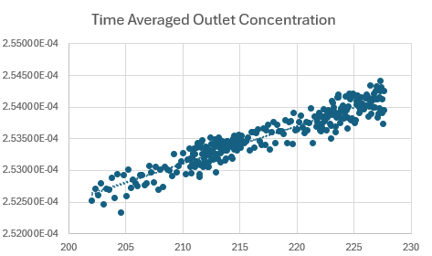
I want to model the species removal from the liquid phase to the gas phase through mass transfer. However, I am confused and concerned if the dirty gas phase is leaving the domain. I am plotting the area-averaged concentration of the species in the liquid phase at the outlet over time and it is slowly increasing. I want this value to stabilize for steady-state results.Â
Â
Is their some source/sink or flux term I should enforce at the gas velocity inlet ( acting as an outlet) ?Â
Â
-
April 2, 2024 at 2:49 pm
Rob
Forum ModeratorNot an easy problem to run. A velocity inlet won't allow the liquid out, but setting a velocity outlet may drag the liquid out the top of the model. I'd also be surprised if the liquid wasn't sprayed onto the top of the bed (although I did do the course to design these things in the mid 90s) so you may want to consider that too.Â
Do you need to model the species transfer, or can you consider bed wetting only?Â
-
April 2, 2024 at 3:04 pm
Anthony Bowers
SubscriberI need to consider species transfer. Do you think if i put the max(concentration) at the velocity inlet, acting as an outlet due to negative velocity with back flow at outlet, this will work?Â
-
April 2, 2024 at 3:38 pm
Anthony Bowers
SubscriberThe simulation is in counter flow. As I have set the gas velocity to be negative to indicate leaving the domain. While the pressure outlet at the bottom having gas back flow for re-entrance into the domain. My only concern is that the species is not leaving the domain with the gas phase.Â
-
-
April 2, 2024 at 3:39 pm
Rob
Forum ModeratorThe species concentration shouldn't matter on the outlet, it's working out how to get the liquid out of the inlet that's the problem. Multiphase and boundaries can get messy as the "other" phase can block the boundary.Â
As an aside, how are you planning on mimicking the surface contact area of the bed packing for the mass transfer?Â
-
April 2, 2024 at 3:43 pm
Anthony Bowers
SubscriberI have got the liquid flowing out the inlet correctly as the boundary next to it is a velocity inlet, gas phase. I am capturing the interfacial area concentration through Simminiceanu analytical model.Â
Â
Liquid flows down while gas flow up by re-entrance at the bottom.Â
The work is similar to this paper Porous media Eulerian computational fluid dynamics (CFD) model of amine absorber with structured-packing for CO2 removal
-
April 2, 2024 at 3:46 pm
Anthony Bowers
SubscriberThe real problem is that i need to specify a zero gradient of species at the gas velocity inletÂ
-
April 2, 2024 at 4:13 pm
Rob
Forum ModeratorYou set the volume fraction for the inlet, on the outlet Fluent ought to remove all of the phase at the rate you set. If you're seeing a diffusion effect turn it off in the species panel.Â
-
April 2, 2024 at 4:28 pm
Anthony Bowers
SubscriberIs their a way to enforce a zero species gradient on a velocity inlet? This is what I need.Â
-
-
April 3, 2024 at 9:09 am
Rob
Forum ModeratorYou can turn off inlet diffusion, otherwise just set the value you want at the boundary.Â
-
- The topic ‘Species Velocity Outlet’ is closed to new replies.
- How do I get my hands on Ansys Rocky DEM
- Unburnt Hydrocarbons contour in ANSYS FORTE for sector mesh
- convergence issue for transonic flow
- Facing trouble regarding setting up boundary conditions for SOEC Modeling
- Point exception in erosion calculation
- Errors with multi-connected bodies using AQWA
- Script Error Ansys
-
2502
-
931
-
761
-
599
-
591
© 2025 Copyright ANSYS, Inc. All rights reserved.