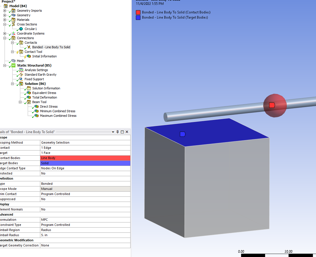
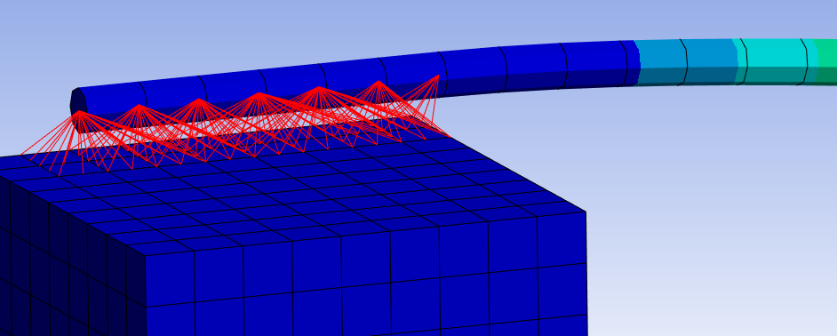
Q1.How to connect a part of a beam, for example, its nodes, to the surface of a solid in contact or joint?
A1: It is not possible to share or connect the nodes of a SOLID body with the nodes of a SURFACE or LINE body. This must be done with Contact Elements.
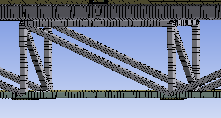
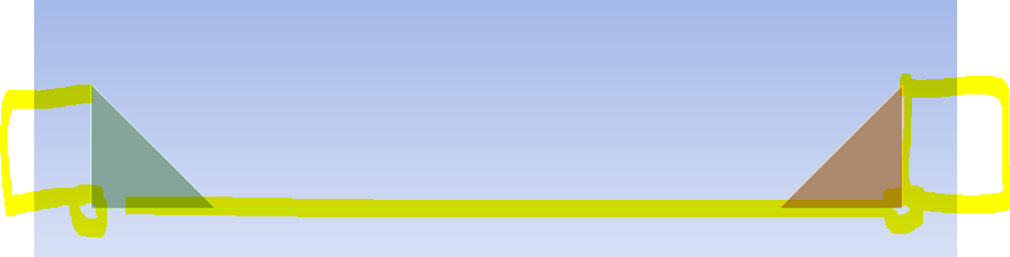
2.What to do if two profile pipes run in parallel, they stand on top of each other, but after turning their beams, they have a space between the lines.
A2: It is not possible to share or connect the nodes of a LINE body that is parallel to another LINE body. This must be done with Contact Elements
Comment: The Beam Cross Section solids are graphical representations only. There are no faces on the line bodes to select as we have with SOLID bodies.
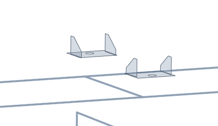
3.If there is a gusset between two corner beams, after turning the pipes into lines, the gusset will hang in the air.
A3: You would have to move and or trim the gusset in order for the LINE and SURFACE edge to be coinsident. (This can be a very tedious process to do manually.)
4.How to connect shells and beams correctly?
A4: LINES and SURFACE edges can only share or connect nodes if they are coincident. This connection must be done with Contact Elements
5.When I SHARE beams in Space Claim, they are combined in the project.
A5: SHARE means it will combine the beam endpoints to connect the mesh.
Any sort of sharing of nodes is done in a Part group.
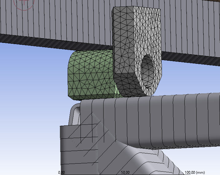
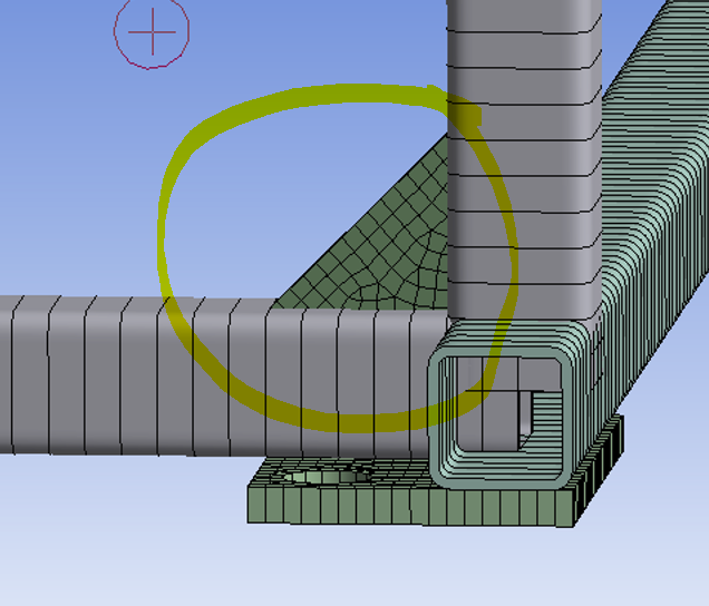
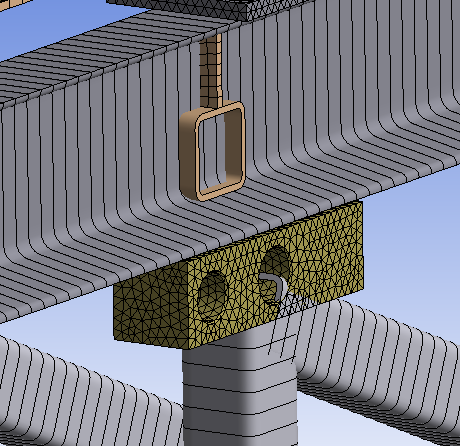
6. Do the intersections of beams with solidamias as in the picture affect the calculation?
A6: No it should not affect calcualtions. Similar to A2, the Beam Cross Section solids are graphical representations only.
The Beam Cross Section solids are graphical representations only.
7.What to do when the pipes are in solids and there is a scarf between two intersecting pipes.
A7: Like A3 you would have to move and or extend the surface for the LINE and SURFACE edge to be coinsident. (This can be a very tedious process to do manually.)
In practice, it is not always practical to decompose a 3D solid geometry into LINE and SURFACE bodes.