-
-
May 25, 2023 at 5:07 pm
K Kramer
SubscriberIn the model below, I always get a solver pivot error although the end node of the beam has a fixed support applied to it. In SpaceClaim, Share Topology is set to "Merge" or "Share" (makes no difference). What is the reason for that? Do I still have to define some sort of connection between the beam and the solid?
Also, I would like to know how exactly the connection between solid and beam is established (since the beam has only one node in the intersection plane while the solid has many).
-
May 26, 2023 at 1:09 am
peteroznewman
SubscriberRight click on the Connections folder and Insert a Fixed Joint. Select the flat face of the solid cylinder as the Reference side of the joint and select the vertex of the beam element that is touching that face as the Mobile side of the joint. The joint will allow the face and vertex to be connected in a way that transmits shear forces and bending moments from the solid to the beam.
-
May 26, 2023 at 6:07 am
K Kramer
SubscriberHi Peter,
thanks for your answer. When I select the end vertex of the beam, Body is set to multiple and the joint does not get a green check (selecting the vertex on the other end does work). I assume that is due to the shared topography? Should I disable it? That leaves me a bit confused since in this demo, topography sharing seems to work without extra steps: https://www.ansys.com/de-de/resource-center/video/beam-and-shell-modeling-with-ansys-mechanical
-
May 26, 2023 at 1:12 pm
peteroznewman
Subscriber
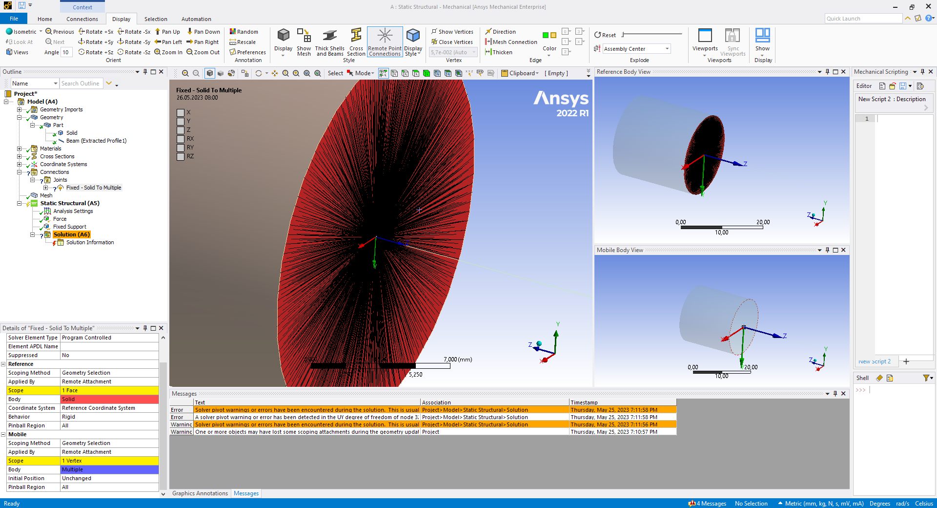
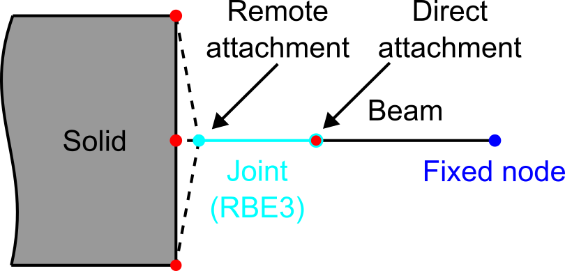
Yes kramer, go back to SpaceClaim and Unshare the geometry. The Joint needs a node at the vertex of the line body that is not shared with a node on the face of the solid.
Shared Topology works between beam and shell elements. It seems confusing why a beam and a solid element doesn’t work, so I will try to explain.
Nodes on beam and shell elements have 6 unknowns (x, y, x, Rx, Ry, Rz), three displacements and three rotations.
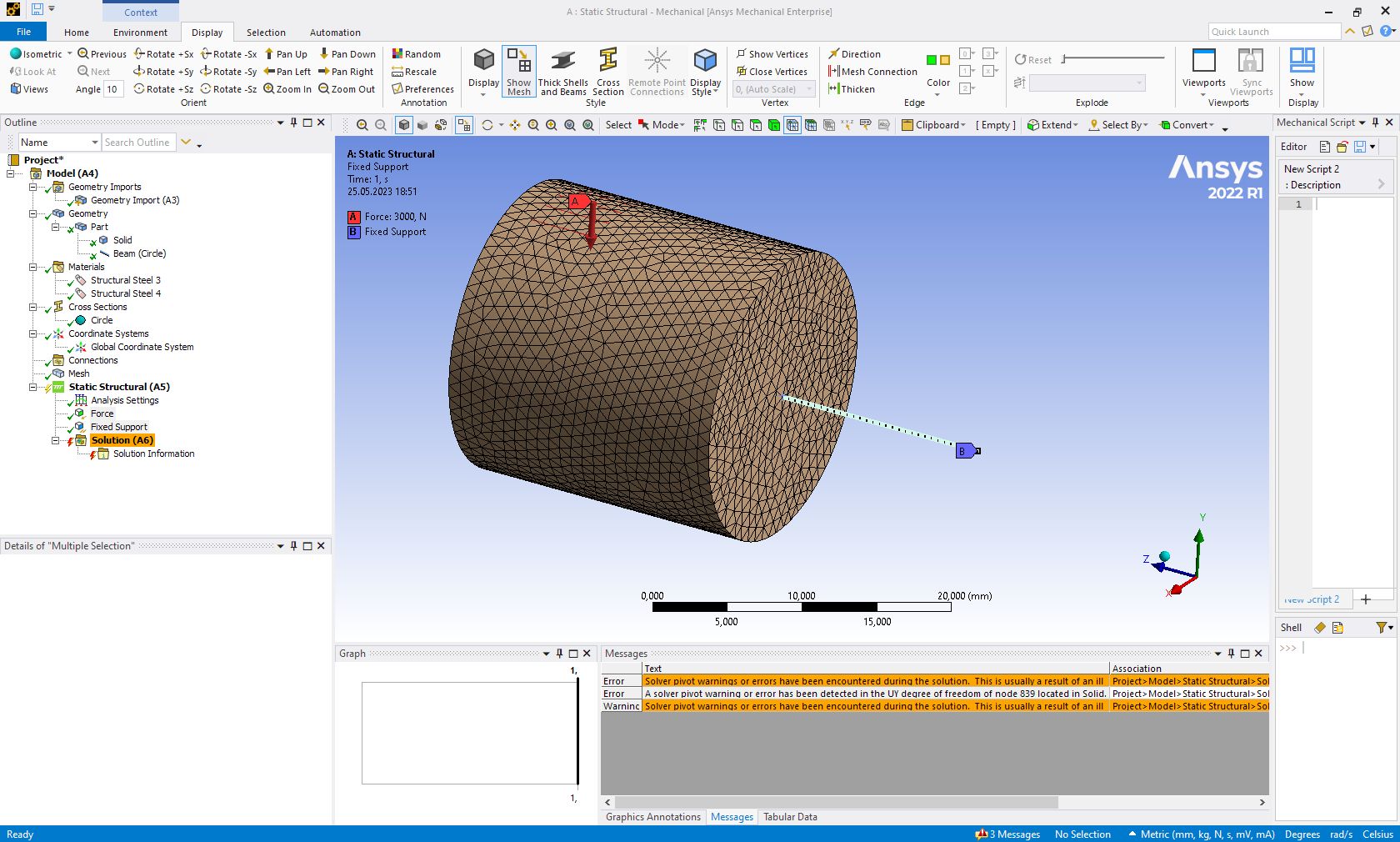
Nodes on solid elements have only 3 unknowns (x, y, z), three displacements. That means when a single node on a beam element is shared with solid elements, the beam behaves as if there is a spherical joint at that node because there is no rotational unknown on the solid elements to support rotational loads.
The same problem happens when a straight line at the edge of a surface is shared with a solid: a hinge would be created.
-
May 27, 2023 at 8:45 am
K Kramer
SubscriberOk, did that. Should I set behavior to rigid or deformable? Empirically, deformable seems to give more realistic results.
-
May 27, 2023 at 10:16 am
peteroznewman
SubscriberBehavior = Rigid forces the solid to behave more like a beam element, since the cross-section of a beam can't change, it can only translate and rotate.
-
May 27, 2023 at 10:44 am
K Kramer
SubscriberÂ
Â
But rigid forces the solid cross section to move as one, right? Thus it would add artificial stiffness. I tried both rigid and deformable. The normal z-stress with deformable is very close to the analytical result (57.3 MPa for a force of 3 kN, a diameter of 20 mm and a distance of approx. 15 mm from load to end of solid), while the result with rigid is almost twice as high.
Â
Â
Â
-
May 27, 2023 at 10:45 am
-
May 27, 2023 at 10:48 am
K Kramer
SubscriberBy the way, I get the following warning: "Joints are being used in the current analysis with Large Deflection turned Off. Â Thus, only linearized joint behavior will be considered. Â If finite rotation and large deflection effects are to be considered, please turn on Large Deflection."
But that should be ok, right?
-
May 27, 2023 at 2:55 pm
peteroznewman
SubscriberRigid elements often cause a stress concentration. That is why they should not be used in a region where accurate stress is needed. You can use deformable if it gives you a better result.Â
I expect the analytical equation does not account for large deflection.
It looks like there is a face on the solid cylinder where no force is applied. This makes the resultant force move from the center of the solid length. Did you account for that in the analytical result?
What is the analytical equation? Â
Where are you looking to evaluate the stress?
Is it at the plane where the solid meets the beam? It is recommended to transition from solid to beam at a different location from where you want to evaluate stress.
Is the beam cross-section the same as the solid?
Why are you switching from beam to solid elements?
What is the result if you just use beam elements?
-
June 11, 2023 at 10:57 am
K Kramer
SubscriberTook a while until I had time to get back after it. I tried a second model for confirmation. Observations hold.
Regarding your remarks:
- I expect the analytical equation does not account for large deflection. -> That is correct, but looking at the stress magnitude, assuming "negligable deformations" is justified (material is steel)
- It looks like there is a face on the solid cylinder where no force is applied. This makes the resultant force move from the center of the solid length. Did you account for that in the analytical result? -> Yes. The distance from the center of force application to the end of the solid is 25 mm.
- What is the analytical equation? -> Bernoulli beam. Force F = 6000 N in z, diameter d = 30 mm, length from center point of force to evaluation point l = 25 mm. Bending stress sigma_b = M_b / W_b =(F * l) / (pi/32 * d^3) = 56,59 N/mm^2
- Where are you looking to evaluate the stress? Is it at the plane where the solid meets the beam? It is recommended to transition from solid to beam at a different location from where you want to evaluate stress. -> Yes, in the transition plane from solid to beam. Of course I could extend the solid, but that would mean more DOFs and thus computation time.
- Is the beam cross-section the same as the solid? -> In this example, yes.
- Why are you switching from beam to solid elements? -> When modelling e. g. a shaft, the true stress at the transition from one segment to another may be of interest.
- What is the result if you just use beam elements -> Didn't try that for the aforementioned reason, but I'd expect it to match the analytical solution pretty well.
Bending stress "flexible":
Bending stress "rigid":
So "rigid" creates, well, rigid links between the DOFs, but how exactly does "flexible" work?
-
June 11, 2023 at 2:56 pm
peteroznewman
SubscriberEuler-Bernoulli beam theory does not include shear deformation so there is no shear stress in your analytical result. Shear stress is negligible in long, slender beams, but you have a non-slender beam so shear stress is significant. Use Timoshenko beam theory to include shear deformation.
Ansys Beam elements use Timoshenko beam theory, and solid elements develop shear deformation, so that introduces a source of error from the Euler-Bernoulli analytical result.
Deformable or "flexible" joints use an element called RBE3 for small deformation analysis. Here is what the Ansys Help guide says about that element.
RBE3 distributes the force/moment applied at an independent node to a set of dependent nodes, taking into account the geometry of the dependent nodes as well as weighting factors. The force is distributed to the dependent nodes proportional to the weighting factors. The moment is distributed as forces to the dependent nodes; these forces are proportional to the distance from the center of gravity of the dependent nodes times the weighting factors. Only the translational degrees of freedom of the dependent nodes are used for constructing the constraint equations. Constraint equations are converted to distributed forces/moments on the dependent nodes during solution.
RBE3 creates constraint equations such that the motion of the independent node is the average of the dependent nodes. For the rotations, a least-squares approach is used to define the "average rotation" at the independent node from the translations of the dependent nodes.
-
June 11, 2023 at 7:08 pm
K Kramer
SubscriberI should have just said "beam" (after all, bending stress does not depend on Bernoulli/Timoshenko and first order theory is applicable in both cases).
Ok, so the "reference" side would be dependent and the "mobile" vertex independent, right? What are the values of the weighting factors (all 1)?
One more question: What is the difference between "remote" and "direct" attachment?
Thanks a lot for your help.
-
June 11, 2023 at 9:18 pm
peteroznewman
SubscriberThe end of the line has a vertex and there is a node at that vertex, so you can use a Direct attachment to the Reference side. The Mobile side is a face with lots of nodes, so you need an independent node to gather the motion of all the nodes into a single node that can be called a Remote Point because there may not be a face node at that location.
I think the weighting factors are 1 but I’m not sure.
-
June 12, 2023 at 8:02 am
K Kramer
SubscriberÂ
So the joint is an RBE3 element? I actually had the mobile side on the beam vertex and the reference side on the solid (both with remote attachment) and it still worked. What difference does that make?
The way you describe it, direct attachment should only work on one node, right? That would mean the node becomes a joint node. But how is the remote node created in the case of remote attachment? Via an extra RBE3 element?
Â
And how could large deformations be handled?
-
June 12, 2023 at 3:30 pm
peteroznewman
SubscriberThe RBE3 element is only valid for small deflections. Ansys automatically uses a different method when large deflections are turned on.
You are free to switch the Reference side and the Mobile side of a Fixed Joint. The Reference side is where the Reference coordinate system is created. In your diagram above, where the beam node has a gap to the face, the coordinate system would be in a different location and so the moments and forces would be different if you switched roles. In your model, the beam node is at the centroid of the face so the coordinate system will be in the same location no matter which way you choose Reference and Mobile, but the signs on the Forces will change if you switch Reference and Mobile.
If you create a Fixed Joint to connect two Faces, then each face gets a Remote Point to gather the nodes on each face to a new node. The two new nodes exist at the origin of the Reference Coordinate System. In the case of two faces, you can't do direct attachment.
-
June 12, 2023 at 4:04 pm
K Kramer
SubscriberThe gaps in the sketch above are just for illustrative purposes. So in the end the only thing that changes when swapping reference and mobile side is the coordinate system (which makes no physical difference)?
From what I understand, the remote point for the face (in case of remote attachment) is created via an RBE3 element and then rigidly connected to the node on the other side (on the beam in this case). For the beam, direct and remote attachment are the same because a remote point would just be a duplicate of the end node, right?
-
June 12, 2023 at 6:00 pm
peteroznewman
SubscriberSwapping Mobile and Reference sides will change the sign of the Force output of the Joint.
For the beam, there is an extra node and an extra element compared with direct attachment.
-
June 19, 2023 at 1:37 pm
K Kramer
SubscriberOk, so to sum it up:
- For remote attachment the remote node is created via an RBE3 element which gathers the interface nodes into one (its behavior will be flexible or rigid depending on which is selected)
- Direct attachment only works for one-node interfaces
- If the interface has just one node, there is no physical difference between remote and direct attachment since a remote node will behave in the same way as the original node
- For a fixed joint, the two resulting nodes (one on each side) are rigidly connected
Is that correct?
-
June 20, 2023 at 3:07 am
peteroznewman
SubscriberRBE3 is only one of a few element types that will be used to gather interface nodes into a pilot node. RBE3 is used for Flexible connections with small deflections. MPC constraint equations will be used for Rigid connections. Contact elements will be used for flexible connections with large deflections. If you look at the ds.dat file in the solver directory, you can see what exactly was created.
-
- The topic ‘Solver pivot error with solid/beam model’ is closed to new replies.
-
3442
-
1057
-
1051
-
917
-
896
© 2025 Copyright ANSYS, Inc. All rights reserved.