-
-
March 16, 2020 at 1:34 pm
Daniel97Yii
Subscriber
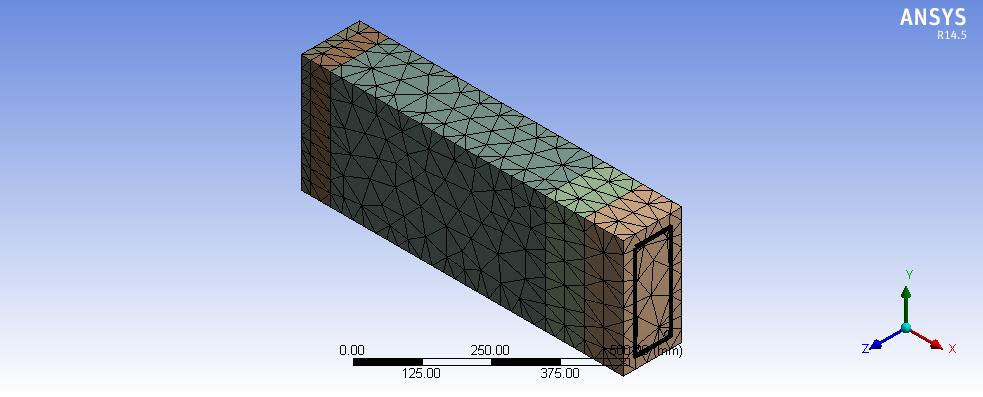
I'm modelling a half RC beam, as shown.
This is the material command for concrete:
et,matid,solid65
MP,Ex,matid,24000
MP,Prxy,matid,0.2
MP,Dens,matid,2320e-9
TB,concr,matid
tbdata,1,0.3,1,0.304,25
This is the material command for reinforcement:
ET,MATID,LINK180
MPDATA,EX,MATID,2e5
MPDATA,PRXY,MATID,,0.3
TB,BISO,MATID,1,2
TBDATA,,500,2100
R,MATID,6,,0
Mesh settings:
1. For concrete, Patch conforming method, tetrahedrons, element midside nodes dropped.
2. For reinforcements, Body sizing, 1mm, soft behaviour.
Symmetry: Symmetric region applied at the face of the middle of the beam.
Analysis settings:
1. Solver controls
Solver type, weak springs- program controlled, large deflection & intertia relief- off.Â
2. Non-linear controls
Force & displacement convergence- on. The rest under non-linear controls are program controlled.
Preprocessor command:
/PREP7
ESEL,S,ENAME,,65
ESEL,A,ENAME,,180
ALLSEL,BELOW,ELEM
CEINTF,0.001
ALLSEL,ALL
/SOLU
OUTRES,ALL,ALL
Displacement applied on the edge of "add frozen" concrete body. Free only at x-direction, constant at y & z direction.
Solver Output:
*** ERROR ***Â Â Â Â Â Â Â Â Â Â Â Â Â Â Â Â Â Â Â Â Â Â Â Â Â Â CP =Â Â Â Â Â 18.422Â Â TIME= 21:23:01
 Solution not converged at time 1 (load step 1 substep 1).             Â
 Run terminated.                                                      Â
 *** WARNING ***                        CP =     18.422  TIME= 21:23:01
 The unconverged solution (identified as time 1 substep 999999) is     Â
 output for analysis debug purposes. Results should not be used for   Â
 any other purpose.                                                    Â
        R E S T A R T  I N F O R M A T I O N
 REASON FOR TERMINATION. . . . . . . . . .UNCONVERGED SOLUTION                  Â
 RESTART BY RE-RUNNING THE ANALYSIS
Above are the details of the model settings, which doesn't yield proper result. Please guide me through my problems. I'm not sure how to rectify the error.Â
Below are the deformation response under this setting:
View in 1.0 (True scale) (above image)
View in 5x (Auto)
-
March 16, 2020 at 3:34 pm
peteroznewman
SubscriberIn Workbench, under Analysis Settings, turn on Auto Time Stepping.
Set the Initial and Minimum Substeps to 100 and the Maximum Substeps to 200.
-
March 17, 2020 at 4:24 am
-
March 17, 2020 at 2:15 pm
peteroznewman
SubscriberYou have to set the Mesh Element Order to Linear if you want to use 8 node hex elements and you have to set the Element Order to Quadratic if you want to use 20 node hex elements. You have left it Program Controlled and it meshed with an element order that does not match the SOLID65 element type. Furthermore, if the element type is only a Hex element, you can't allow the mesh to have any Tetrehedral shapes (and vice versa).
SOLID65 is an obsolete element. I can't even find it in the 2019 R3 help system. Consider changing to a current technology element.
-
March 18, 2020 at 1:50 am
-
March 18, 2020 at 4:25 am
peteroznewman
SubscriberSOLID65 is a Linear element so set the Mesh to use Linear elements.
-
March 18, 2020 at 4:33 am
Daniel97Yii
SubscriberMesh settings:
1. For concrete, Patch conforming method, tetrahedrons, element midside nodes dropped.
2. For reinforcements, Body sizing, 1mm, soft behaviour.
If I have not mistaken, element midside nodes dropped= linear?
-
- The topic ‘Solution not converged (Symmetric RC Beam)’ is closed to new replies.
- The legend values are not changing.
- LPBF Simulation of dissimilar materials in ANSYS mechanical (Thermal Transient)
- Convergence error in modal analysis
- APDL, memory, solid
- How to model a bimodular material in Mechanical
- Meaning of the error
- Simulate a fan on the end of shaft
- Real Life Example of a non-symmetric eigenvalue problem
- Nonlinear load cases combinations
- How can the results of Pressures and Motions for all elements be obtained?
-
4017
-
1461
-
1287
-
1135
-
1021
© 2025 Copyright ANSYS, Inc. All rights reserved.