-
-
February 18, 2026 at 1:20 pm
hakkeemnazar007
SubscriberHello everyone,
I am currently working on a hydrofoil model using a NACA 63412 profile. I designed the geometry in Rhino 3D, then imported it into ANSYS SpaceClaim, and proceeded with the laminate definition in ACP (Pre) using shell elements for the foil surfaces.
After defining the plies and generating the ACP solid model, I am facing an issue:
- The top and bottom solid models are not properly connected
- There appears to be a gap/opening along the mid-plane region
- When transferred to Static Structural, the solid behaves as two separate bodies
- Under load application, the structure does not act as a single connected foil
My modeling workflow was:
- NACA 63412 geometry created in Rhino 3D
- Imported into SpaceClaim (STEP format)
- Shared topology applied
- ACP shell model created
- Cutoff plane defined at mid-surface
- Solid model generated using extrusion guides
However, during solid generation:
- I receive intersection and tetrahedron decomposition warnings
- Some bad elements are deleted automatically
- The final solid mesh shows separation along the mid-plane
As a result, the structure is not continuous when transferred to Static Structural.
I would appreciate guidance on:
- Proper cutoff plane definition for symmetric foil laminates
- Correct extrusion guide setup in ACP
- Best practices to ensure top and bottom solids merge into a single continuous body
- Whether this is a geometry tolerance issue from Rhino import
- Recommended solid model generation settings in ACP
I can provide the project files (.wbpj / ACP model / geometry) if required.
Thank you very much in advance for your help.
Kind regards
Hakkeem NazarÂ
Â
-
March 11, 2026 at 7:00 pm
Raman Babu
Ansys EmployeeHello,
Since this is a solid aerofoil structure, please start with a center shell plate and lay plies toward the topside and bottom side.
While generating the solid, you can use either the cut-off geometry or the snap-to-geometry option to capture the actual shape of the structure.
Please try this approach and let me know how it goes.
Regards,
Raman BabuÂ
-
March 11, 2026 at 7:19 pm
hakkeemnazar007
SubscriberHello Raman,
Thank you for your reply and the suggestion.
Just to confirm if I understood your approach correctly:
Since this is a solid aerofoil structure, should I first start with a center shell surface (mid-plane) as the main geometry and then define the laminate layup starting from the core layer, followed by the carbon plies toward the top and bottom of this surface?
And for generating the solid model in ACP, do you mean that I should:
1. Import the center plane geometry of the foil as the initial reference surface.
2. Define the laminate layup on this mid-surface.
3. Then use the foil top and bottom surfaces as the Cut-Off Geometry or Snap-to-Geometry when generating the solid model so that the laminate conforms to the aerofoil shape.
Is this the workflow you are referring to?
Thank you again for your guidance.
Best regards,
Hakkeem Nazar
-
March 12, 2026 at 3:50 am
Raman Babu
Ansys EmployeeHello Hakkeem,
Yes, you are correct.
Please try it and let me know how it goes.
Regards,
Raman Babu
Â
Â
-
March 12, 2026 at 2:13 pm
hakkeemnazar007
SubscriberHello Raman,
Thank you very much for your suggestion.
I would like to clarify my understanding and explain the difficulty I am facing.
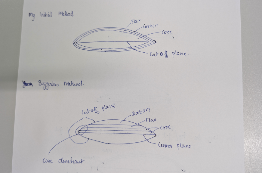
Initially, my workflow was the following: I used the top and bottom foil surfaces as the reference shell geometry, and defined the laminate plies growing inward from both sides. The center plane of the foil was then used as the cut-off geometry when generating the solid model. However, with this method the top and bottom solid parts were not connecting properly, which is why I asked the question in the forum.
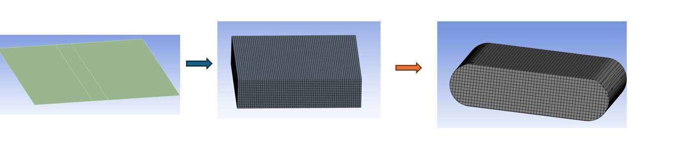
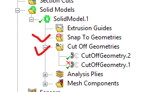
From your reply, I understood that the better approach is to start with a center shell surface (mid-plane) and then define the laminate layup from this reference surface toward the top and bottom directions, using the foil outer surfaces as cut-off or snap-to geometry when generating the solid.
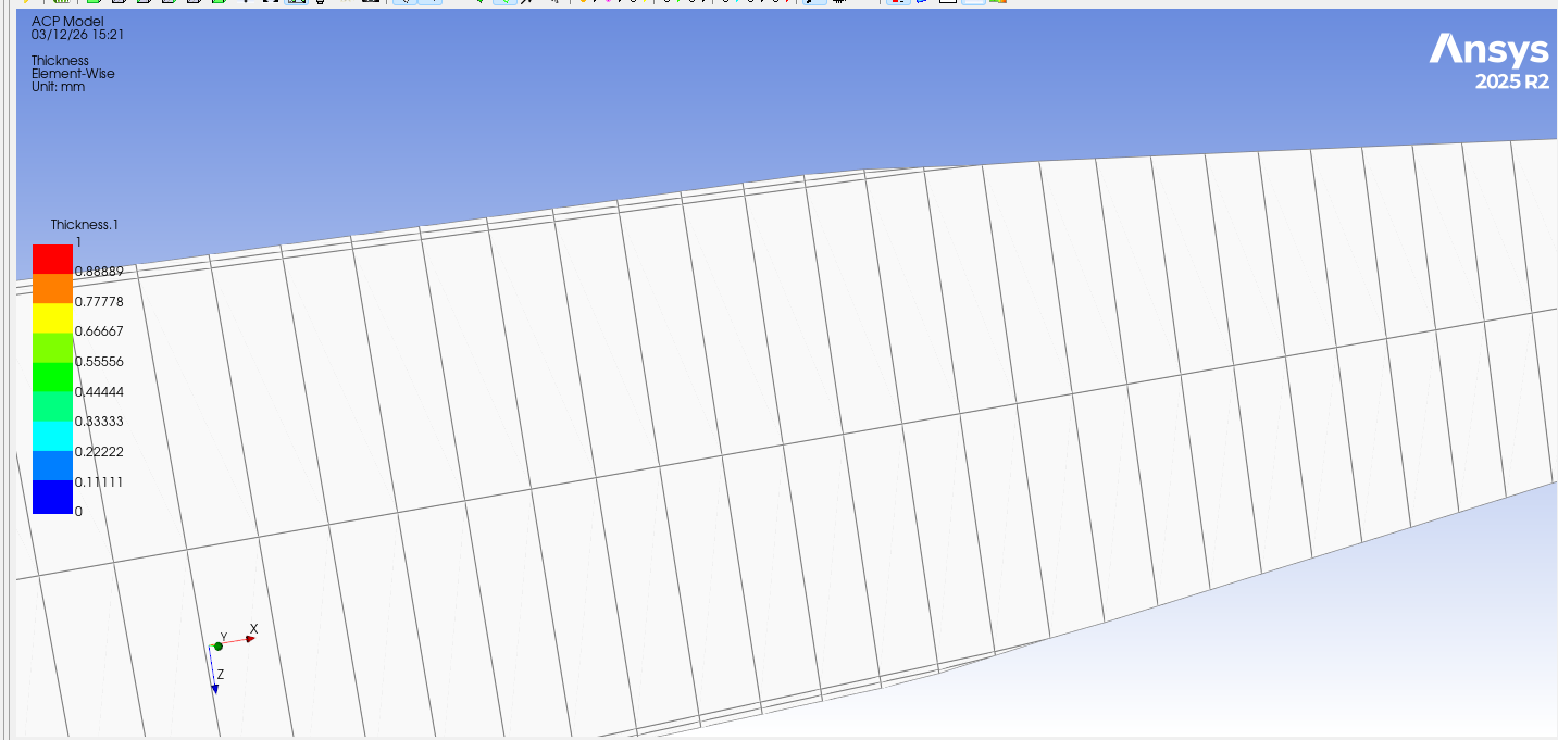
However, I am facing a conceptual issue with this approach. In my case the laminate is a sandwich structure (carbon/flax skins with a foam core). If I start from the mid-plane and define the core layer first, it effectively becomes a solid block in the middle, and near the leading edge and trailing edge the core may reach the outer boundary of the foil geometry.
In reality, the outer aerodynamic surface should be the carbon/flax skin layers, not the core material. Therefore, I am unsure how the correct skin-core-skin structure should be preserved near the leading edge and trailing edge when using the mid-plane approach.
I have attached a simple sketch illustrating the two approaches I described for better clarity.
Thank you again for your guidance.
Best regards,
Hakkeem NazarÂÂ
-
March 12, 2026 at 2:22 pm
-
March 12, 2026 at 2:28 pm
hakkeemnazar007
SubscriberHello Raman,
I am currently trying to follow this approach, but I am still facing some difficulties in implementing it correctly in ACP. I have been stuck on this issue for almost one month now.
Could you kindly help me understand how to properly model this so that the solid model is generated correctly?Â
Your guidance would be greatly appreciated.
Best regards,
Hakkeem NazarÂ
-
March 17, 2026 at 12:39 am
hakkeemnazar007
SubscriberHello Raman,
I hope you are doing well.
I just wanted to follow up regarding my previous query. I am currently waiting to hear from you, and I would really appreciate your guidance on this issue.
I am a bit stuck at this stage, so it would be very helpful if you could kindly provide some support whenever you have time.
Looking forward to your response.
Best regards,
Hakkeem Nazar
-
- You must be logged in to reply to this topic.
-
5834
-
1906
-
1420
-
1305
-
1021
© 2026 Copyright ANSYS, Inc. All rights reserved.


