-
-
October 3, 2024 at 8:18 am
ahmet.yildirim
SubscriberDear Recipient,
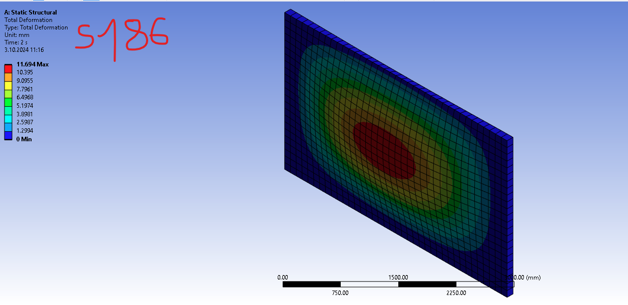
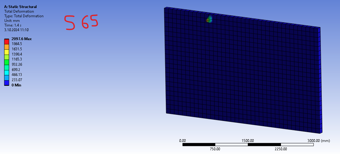
The model given in the picture results differently for solid 65 and solid 186. It can be understood that these elements are different behaviours but why this results are obtained I did not figure out?
Just description of the model: Pressure (0.1 MPa) at the top, fixed at the bottom and simply supported at each side and at top except y-dir to apply pressure effect. Then remote-disp (4 mm) at the face in the direction out-of-plane let's say normal to the surface.
Also, material data: Just Elastic Modulus, Density and Poisson ratio.
The results is OK with Solid 186 element but it was not the same with Solid 65 (or Solid 185 I tried).
Pictures can be found below (First Solid 186 and then Solid 65 element result):
Â
Looking forward to your response,
Regards,
Ahmet YILDIRIM
-
October 7, 2024 at 3:26 pm
Tasos Zacharakis
Ansys EmployeeHello Ahmet,
Â
Take a look at the assumptions and restrictions of solid65 at : SOLID65 (ansys.com).
Hope that helps.
Â
Thank you,
Tasos
-
- You must be logged in to reply to this topic.
- The legend values are not changing.
- LPBF Simulation of dissimilar materials in ANSYS mechanical (Thermal Transient)
- Convergence error in modal analysis
- APDL, memory, solid
- How to model a bimodular material in Mechanical
- Meaning of the error
- Simulate a fan on the end of shaft
- Nonlinear load cases combinations
- Real Life Example of a non-symmetric eigenvalue problem
- How can the results of Pressures and Motions for all elements be obtained?
-
3882
-
1414
-
1241
-
1118
-
1015
© 2025 Copyright ANSYS, Inc. All rights reserved.