Ansys Products

Ansys Products

Discuss installation & licensing of our Ansys Teaching and Research products.

Solar Load Model on ANSYS Fluent

    • Celine Lim
      Subscriber

      Hello,

      I am running a solar model and have some questions regarding absorptivity/emissivity definitions in the solar load model. 

      I am using solar ray tracing currently. I understand that solar ray tracing doesn't take part in radiative heat transfer modeling, and merely taking the solar boundary condition as a heat flux input. However, we do still have the option to set semi-transparent and opaque surface for our model. Attached is a figure of my current model in Fluent. 

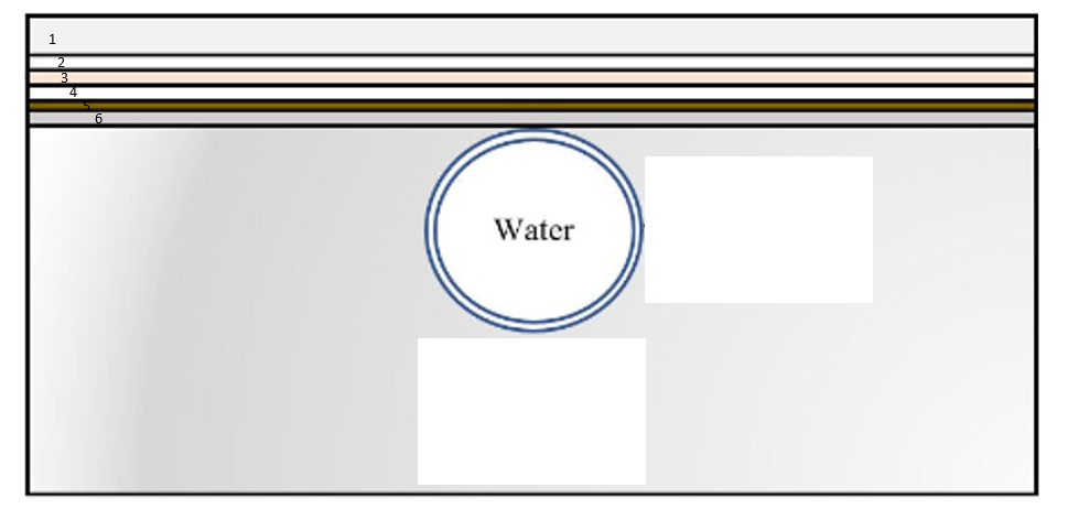
      Body 1 is a surface that takes solar irradiation, defined in the solar load model. This is a semi transparent surface with absorptivity and transmissivity defind.

      Body 2 is also a semi-transparent surface with absorptivity and transmissivity defined.

      Body 3 is an opaque surface with absorptivity defined.

      Body 4 is a semi-transparent surface with absorptivity and transmissivity defined.

      Body 5 is a semi-transparent surface with absorptivity and transmissivity defined.

      Body 6 is an opaque surface with absorptivity defined.

      Water acts as a heat sink in this model. 

      Now my goal with my this study is to change the absorptivity of material surface 6. What I would expect from this study is that with higher absorptivity on the surface of body 6, I would get higher water temperature as well as higher temperature for body 6. However, it seems like it is the opposite of this. Keeping all my other BCs constant and changing only the absorptivity of body 6 to be a higher value, i found that the average water temperature decreases while the temperature of bodies 1-5 increased, which is the opposite of what I was expecting.

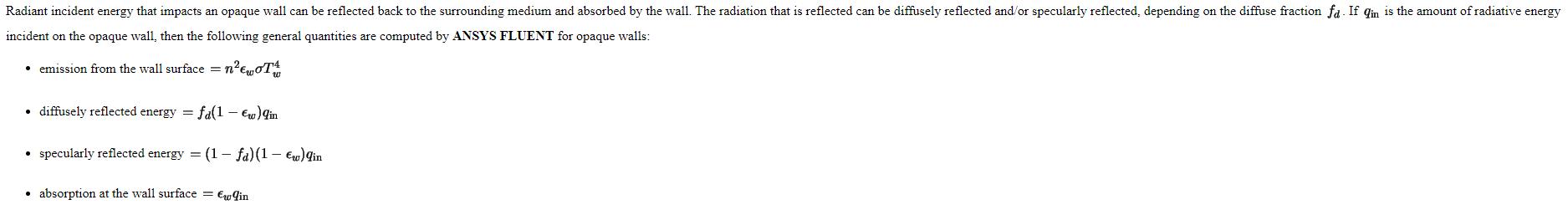
      The only reason I could think of is that Fluent might actually be considering absorptivity = emissivity in this case based on Kirchoff's law. In this case, with higher absorptivity = higher emissivity, and more heat is emitted from surface of body 6 back up, hence the higher temperatures of body 1-5. I know this is true for S2S model, but im not sure if this is the case for solar ray tracing. If anyone has any directions on this, please do advice, thanks. 

    • C N
      Ansys Employee


      Hello,

      The solar ray tracing option has some limitations its effect is negligible if the solar ray tracing model includes only boundary zones that are adjacent to fluid zones in the ray tracing calculation. In other words, boundary zones that are attached to solid zones are ignored. 
       
      So be careful with boundary and set the adjacent side to boundary as a fluid zone . This might be one of the reason why there is no solar load contribution to your problem and also check whether you have activated the energy equation which is coupled to solar load. 


      On enabling the Solar ray tracing option the following things can be observed. The reflection of the direct solar load is explained in detail and how Fluent calculates it.
       Solar Ray Tracing only tracks a ray until it reaches the first opaque wall, after this there is no more ray tracing done and with this no “real” reflection.
       
      In the boundary condition panels for walls absorptivity and (for semi-transparent walls) transmissivity has to be defined. 1 minus these values is the portion which is handled as reflected. The reflected solar flux will summed up and then distributed to the energy sources of all walls (with participation on solar ray tracing activated).
       
      This is also called as internally scattered energy. The fraction of the scattered energy which is distributed to the walls can be changed by the TUI command
       
      /define/models/radiation/solar-parameters/scattering-fraction
       
      The default value is 1 so all reflected energy is distributed. A value of 0 means all reflected energy is just taken out of the calculation.
      I hope this will help you in understanding about how the fluent uses solar load model.
       
      Thanks,
      Chaitanya Natraj


      • Celine Lim
        Subscriber

        Hi Chaitanya,

        Thank you for the explanation, I have a beter understanding now. Just to clarify, if the scattering fraction is changed to 0, this means none of the rays at the BC walls will be reflected and this energy will remain absorbed by the BC? 

        It does seems like the issue is that the solar ray tracing is only capturing the effects up until Body 3 (the first opaque surface) of my model. As I am interested in changing the solar properties (such as absorptivity) of body 6 (which is also an opaque wall), this method of analyzing may not be appropriate. On top of the solar ray tracing, would incorporating  another models, such as a DO model, be more appropriate for this problem? 

        Thank you again,

        Celine


    • Celine Lim
      Subscriber


      Hi Chaitanya,

      Thank you for the explanation, I have a beter understanding now. Just to clarify, if the scattering fraction is changed to 0, this means none of the rays at the BC walls will be reflected and this energy will remain absorbed by the BC? 

      It does seems like the issue is that the solar ray tracing is only capturing the effects up until Body 3 (the first opaque surface) of my model. As I am interested in changing the solar properties (such as absorptivity) of body 6 (which is also an opaque wall), this method of analyzing may not be appropriate. On top of the solar ray tracing, would incorporating  another models, such as a DO model, be more appropriate for this problem? 

      Thank you again,

      Celine


    • C N
      Ansys Employee

      Hello,

      Yes, you are correct when the scattering fraction is set to 0 none of the rays will be reflected and it will all get absorbed. I recommend the DO model with solar ray tracing according to the best practices.

      Thanks,

      Chaitanya Natraj


      • Celine Lim
        Subscriber


        I understand, thank you. I have a follow-up question regarding opaque surfaces.

        As some radiation gets absorbed by a surface, some of it gets emitted too. I believe on Fluent with the DO model we can set the absorptivity of a surface and an internal emissivity. Is there a method to set the emissivity to be on the same side of the surface where absorptivity is applied? Or does Fluent somehow assumes that absorptivity = emissivity for DO models too? I know this is true for S2S and im not sure if this holds true for DO model.

        *edited: 

        I was looking through fluent's manual on DO models (https://www.afs.enea.it/project/neptunius/docs/fluent/html/th/node115.htm), it seems like the model does take absorptivity = emissivity for calculating the radiative energy: 

        For my study, this does not actually hold true for the type of material that I am interested in (this material has different absorptivity and emissivity values). Is there a way where this can be applied on Fluent more accurately? 

        Thank you for your time, 

        Celine  


Viewing 3 reply threads
  • The topic ‘Solar Load Model on ANSYS Fluent’ is closed to new replies.