-
-
February 24, 2023 at 10:11 pm
Maria Fernanda Velasquez
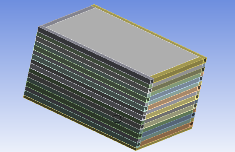
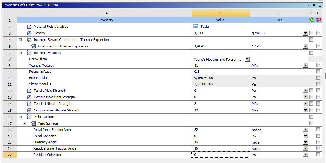
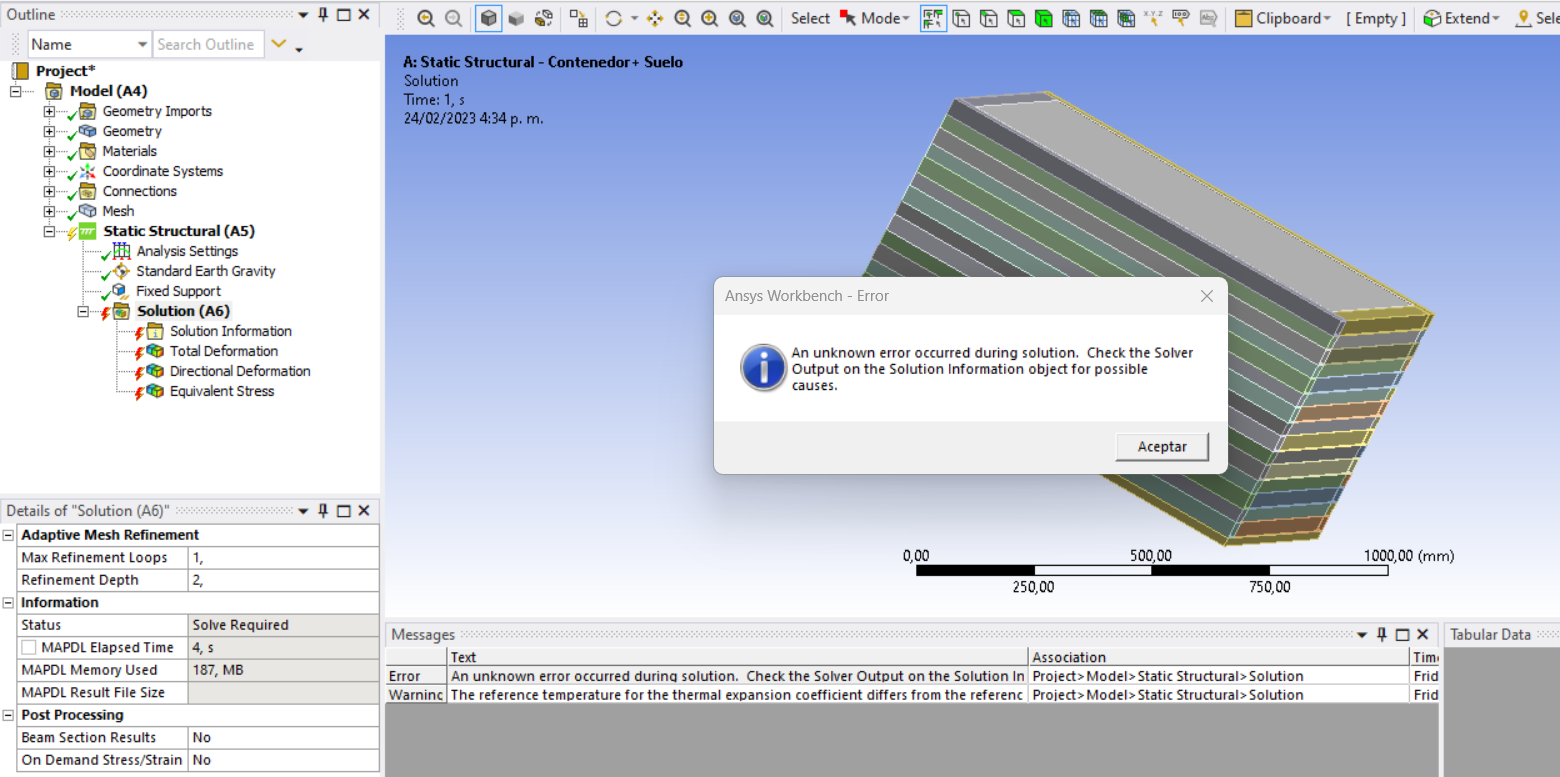
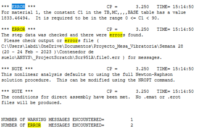
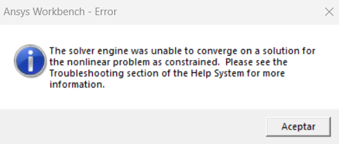
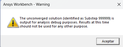
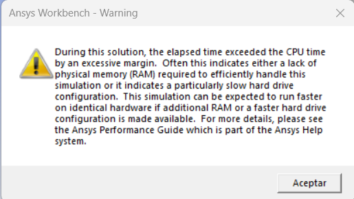
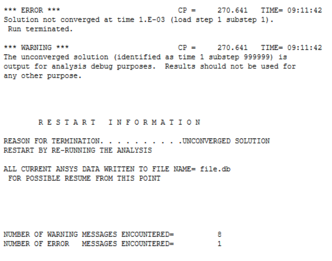
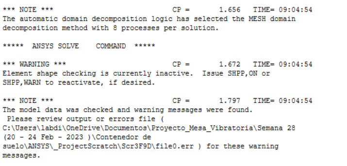
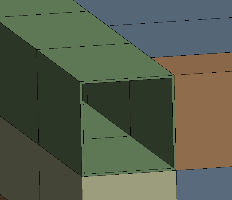
SubscriberGreetings to allI have a difficulty with the model I have in ANSYS.I am modeling a flexible floor container that is built with aluminum profiles and interleaved rubbers supported on a steel plate (Image 1).Inside the container is the floor (for this I create a straight rectangular prism and assign the corresponding material).The material is as follows (Image 2).When I perform the static analysis with the container alone, no problem is generated. However, when I add the floor I get this error and I do not know how to solve it (Image 3 and 4).I emphasize that I am not an expert in ANSYS, I have seen many videos and I have reviewed the picture, but I can't find the cause of my problem.Thank you very much, I hope someone can help me. -
February 24, 2023 at 10:36 pm
-
February 27, 2023 at 2:22 pm
Maria Fernanda Velasquez
SubscriberGreetings Peter
Thank you very much for your help, I have corrected the friction angle units. However, when I run the analysis, I get other alerts as follows:
I tried to increase the mesh size, but this did not work for me. I hope you can help me. Thank you very much for your help.
Regards,
Maria Fernanda
-
February 27, 2023 at 4:38 pm
peteroznewman
SubscriberDear Maria Fernanda,
Try setting up Automatic Time Stepping and using an Initial and Minimum Substep to be 1000. That might help it converge for at least a few substeps.
I have a little experience with the Mohr-Coulomb material model. One way to gain experience with the material model is with a unit cube. Use Frictionless support on three sides of the cube that share one corner. On one opposite face, apply a Displacement load such as a small amount of compression or a small amount of tension. Mesh the cube with 1 linear element so there are only 8 nodes. See what happens.
In the model of the stacked rubber sheets that has rectangular sheet on the bottom representing soil, change the material from soil to a linear elastic isotropic material. Solve this and look at the stress on the sides of the “soil” block. That block has a Fixed Support on the bottom. How is it connected to the rubber sheet touching it? Is it Bonded Contact? Look at the side walls of that “soil” block. Are they bulging out with the weight of the rubber above it? Maybe the reason this model will not converge with a M-C soil material is because stress develops in the material which it cannot support.
What might work is to increase the soil block by 4 times its current dimensions in length, width and depth. Now the side walls are far from the rubber block. Apply a Fixed Support to the side wall of the soil block as well as the bottom face. Please let me know what you find out.
Regards,
Peter
-
February 27, 2023 at 9:26 pm
Maria Fernanda Velasquez
SubscriberGreetings PeterAnswering your two questions (How is it connected to the rubber sheet touching it? Is it Bonded Contact?):All contacts between aluminum sheeting, rubber and steel plate with the soil is bonded contact.I performed the analysis, configuring the Automatic Time Step as you mentioned, however I get the same alerts.I will try to do what you say in your message to better understand the M-C model. But as I am new to the program, I may have some difficulties.Regards,
Maria Fernanda
-
February 27, 2023 at 9:54 pm
peteroznewman
SubscriberGreetings Maria Fernanda,
What version of ANSYS are you working with? Please state the year and the R number. Is it the free Student license with limited nodes and elements or is it an unlimited license?
I reread the original post and may have misunderstood the model on first reading. The soil is inside the container. I see there are aluminum tubes around the sides, and the steel plate is at the bottom. Are the interleaved rubbers the same size as the aluminum tubes? Are the aluminum tube geometry solid bodies with a wall thickness or are they sheet bodies with a thickness property entered in Mechanical?
Bonded contact of the sides of the container to the soil might not be the best way to model the interaction of the soil to the container. Frictional contact might work better.
Regards,
Peter
-
February 27, 2023 at 10:07 pm
Maria Fernanda Velasquez
SubscriberGreetings PeterI answer your questions below- What version of ANSYS are you working with? 2022 R1 - Free Student license
- Are the interleaved rubbers the same size as the aluminum tubes? The rubbers and the aluminum profiles have the same base (where the union of both is), but different height (not very noticeable).
- Are the aluminum tube geometry solid bodies with a wall thickness or are they sheet bodies with a thickness property entered in Mechanical? They are solid bodies with a wall thickness.
Thank you very much for your help
Regards,
Maria Fernanda
-
February 28, 2023 at 1:07 am
peteroznewman
SubscriberGreetings Maria Fernanda,
I'm wondering about the container. You said all the parts are held together with Bonded Contact. This allows the model to solve without the soil, but is this model supposed to represent a real assembly? In a real assembly, are the parts actually glued together? If they are not actually glued together, then any side load on the wall would cause it to topple over. Look at the left wall in the image below. All the aluminum tubes and rubber spacers are the same length and are not attached in any way to the adjacent walls.
If instead the rubber spacers on the left wall were two alumimum tube width shorter, while the rubber spacers on the adjacent walls were two aluminum tubes longer, then the corner edge of the container would have rubber on the short side that reached under a long side aluminum tube. That would help keep the container together with just frictional contact. Hope that makes sense.
At some point, it might be worth replacing the solid bodies for each tube with sheet bodies of the outer faces. That will allow those faces to be meshed with shell elements which will take many fewer nodes and elements than is needed to mesh the solid body of the tubes.
If you can share your model, I can show you what I mean. Use File Archive to save a .wbpz file. Upload that file to your Google Drive (if you use Gmail) or OneDrive or other file sharing service and put the link to that file in your reply. Make sure that the link is for Anyone to download the file.
Regards,
Peter
-
February 28, 2023 at 2:25 pm
Maria Fernanda Velasquez
SubscriberGreetings Peter
I answer your questions below:
Is this model supposed to represent a real assembly? Yes, it's not built yet, but that's the idea.
Are the parts actually glued together? The pieces of aluminum are to be joined by welding (like a frame), and the joint between the rubber and aluminum (in the vertical direction) is intended to be made with screws that hold the pieces joined.
I share the link to the .wbpz file
Link: https://drive.google.com/drive/folders/1yJXSX1q9qj3bL5AsGmP6NgsFfwQ8UcAO?usp=share_link
Regards,
Maria Fernanda
-
February 28, 2023 at 6:01 pm
peteroznewman
SubscriberMaria Fernanda,
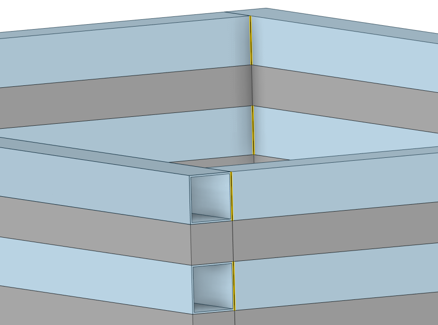
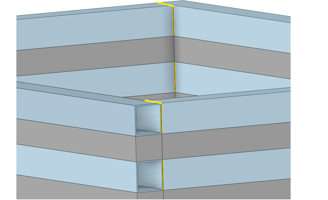
So four pieces of aluminum tube will be welded together to make a frame. Are the welds both on the inside corner and the outside and highlighted in yellow below?
Where are the screws placed? I assume the rubber strips are laid on top of the tube frame, then screws go vertically through the rubber and into the top face of the aluminum tube, but they don’t reach the bottom face of the tube, is that right? Is it just 2 screws, one at each end of the rubber strip?
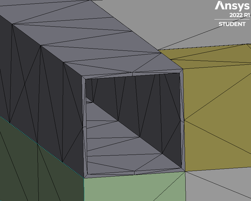
The elements on the tube are not good quality. They have a very high aspect ratio.
You will get better quality elements if you have a tube created by a sheet body with just four faces.
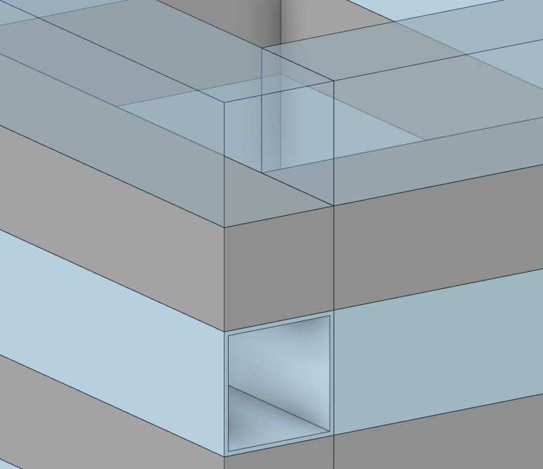
Here is what the geometry looks like without solid tubes for just these top two tubes.
Now the tube is meshed with shell elements and has an assigned thickness. This will use far fewer nodes and elements.
I will address the question of the soil in the next reply sometime later.
Regards,
Peter
-
February 28, 2023 at 6:32 pm
peteroznewman
Subscriber-
February 28, 2023 at 7:10 pm
Maria Fernanda Velasquez
SubscriberThe direction in which gravity is pointing is incorrect, it should be pointing in the -Y direction.
-
-
February 28, 2023 at 6:33 pm
Maria Fernanda Velasquez
SubscriberGreetings Peter
Are the welds both on the inside corner and the outside and highlighted in yellow below? Yes, the welding is on the entire cross section of the aluminum profile, on the outside, inside, top and bottom (see figure).
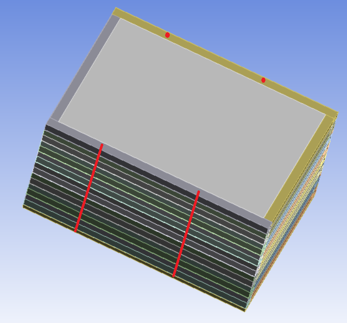
As for the location of the screws, they pass all the aluminum profiles and the rubbers as shown in the figure, from the steel plate.
To go from the solid tubes to a sheet body with only four faces, I can do it transforming the ones I already drew, or I must do it from scratch (I don't have much experience).
I remain pending to the part of the soil.
Thank you very much for helping me so much and for the recommendations you make about the model in general.
Regards,
Maria Fernanda
-
February 28, 2023 at 8:21 pm
peteroznewman
SubscriberGreetings Maria Fernanda,
To learn about the M-C soil model, I suggest starting with the simplest soil model possible. Forget the rubber and the tubes. Make a container that has five surfaces (not solids) and make a solid block to fill it, but make the soil thickness less than the height of the container so that the container walls are above the top of the soil. The bottom of the container can be fixed and the only load is gravity.
Use frictional contact between the soil and the container. See if you can get this simple model to converge. When you do, you will know what is needed to have a working soil model.
Regards,
Peter
-
March 1, 2023 at 10:59 am
peteroznewman
SubscriberGreetings Maria Fernanda,
I built the simple model suggested above to see for myself what it takes to get it to converge. I simplified it even more by making the walls of the container rigid. I could not get it to converge using Standard Earth Gravity so I replaced that with an Acceleration load that begins at 100 mm/s^2 to get convergence started, then ramps the value up to 9800 mm/s^2 which represents the acceleration of Standard Earth Gravity. Ansys 2022 R1 archive.
The next model to investigate is to change the container from rigid to flexible and see what happens. The wall thickness and wall material are easily changed to make it gradually more flexible.
Regards,
Peter
-
March 2, 2023 at 2:29 pm
Maria Fernanda Velasquez
SubscriberGreetings PeterI reviewed the simplified model you shared with me and since I am not that experienced with the software, I need to investigate the different options you use, to better understand and be able to make the changes from rigid to flexible and give it a thickness.I don't know how:How to create the surface.Do you do the gravity increaseThe options you use in contacts and meshing.The APDL commandsIf you have any information (videos or papers) that you can share with me regarding these topics, it would help me a lot to understand. I am going to study that part to understand the model.Additionally, I have some questions:When you mention changing the container from rigid to flexible, do you mean the simplified model you shared with me?Can I modify from my container geometry the aluminum profiles to sheet bodies with only four faces for each one? or should I do it from scratch?Regards,Maria Fernanda
-
March 2, 2023 at 4:42 pm
peteroznewman
SubscriberGreetings Maria Fernanda,
The simplified model I shared with you has a rigid container. Click on the surface under Geometry and look in the Details window. You will see that it is rigid and that can be changed to flexible. Once it is flexible, the wall thickness and material make a difference in how much the walls bend.
A description of the goals for your simulation model would be helpful to decide how best to represent the container to more accurately model the aluminum tubes and rubber strips.
It is easier if I show you how to operate the software to do what I did and answer your questions on the simple model in a Zoom/Skype/Google type meeting where I can share my screen. I could meet with you later today or tomorrow. I am in the Eastern Standard Time Zone where it is 11:42 AM right now. If you want to meet, let me know the day and time you can meet, but give me at least 2 hours notice so I can see your reply and confirm that I am available.
Regards,
Peter -
March 2, 2023 at 8:27 pm
Maria Fernanda Velasquez
SubscriberGreetings PeterI really appreciate your willingness to help me with the difficulties I have encountered.As for getting together to make it easier for me to understand you, that is a very good idea. However, my native language is Spanish (I am Colombian), and my level of English is very low. So it would be very difficult to communicate. I will ask if a friend can act as an intermediary. If you think we can do it this way, or continue through the forum?As for the objectives of the model are the following:The idea is to design a “Flexible” soil container (according to literature and soil container design). In the scientific literature there have been made models similar to the one I am proposing in my design.The idea is that the container is an extension of the soil and that the boundary effects are minimized, i.e., because the soil in reality is not finite, the container should be flexible enough to have the greatest similarity in its behavior as the soil (in my case sand).The idea is to find a geometry (both of the pieces and of the whole container), that allows us to reduce the boundary effects, when an earthquake arrives.Let me know if I was clear enough.Thank you very muchMaria Fernanda Velasquez -
March 2, 2023 at 9:33 pm
peteroznewman
SubscriberGreetings Maria Fernanda,
You will learn a lot watching me operate the software, even if your level of English is low. If your friend can act as a translator, that would be great. I currently have no meetings on Friday, so let me know if you want to schedule a time to meet. You or I can record the meeting so you can review the video after the meeting. We shall also continue to use the Forum.
I understand you want to make a container that represents a similar stiffness to the soil. Is the idea that you want to put this container on a shaker table to simulate an earthquake? Tell me more about the earthquake. A good way to minimize the boundary effects is to make a bigger container and limit the investigation to the soil near the center of the container, far from the walls and bottom of the container.
Regards,
Peter
-
March 2, 2023 at 9:57 pm
Maria Fernanda Velasquez
SubscriberGreetings PeterThank you very much for your willingness.Friday is perfect. We have a time difference of 5 hours. At this moment it is 4:57 pm in Colombia. Tell me what time is good for you and I will adjust to your schedule.The idea is to put the container on the shaking table and induce the seismic. As for the seismic information, I have not yet defined which one I am going to use, most likely it will be one that has a known record and I can verify the results in some way. That part of the modeling I am also investigating to do it in ANSYS.Thank you very muchMaria Fernanda Velasquez -
March 2, 2023 at 10:21 pm
peteroznewman
SubscriberGreetings Maria Fernanda,
Colombia is in the same time zone as New York, we are both in the same time zone. Note that the time in the corner of the posts on this forum is the time in London (GMT), not our local times. I am available 9 AM to noon and 1 PM till 6 PM. What time is convienient for you? Is your friend joining in? What do you usually use for video calls? We can use a Google Meet meeting that I can set up.
I used seismic data in a simulation I worked on a few years ago, so I have some experience with that.
Please reply with just your email address. Wait a minute then EDIT your reply and erase your address from the post. I will get the first line of your original reply in my inbox, then I can send you an email.
Regards,
Peter
-
March 2, 2023 at 10:30 pm
Maria Fernanda Velasquez
SubscriberGreetings Peter
The meeting can be done by Meet and Greet and 1 PM is fine.thank you very muchMaria Fernanda Velásquez
-
March 2, 2023 at 10:50 pm
peteroznewman
SubscriberGreetings Maria Fernanda,
I have your email address. I will send you a meeting invite soon.
Regards,
Peter -
March 3, 2023 at 8:41 pm
peteroznewman
SubscriberGreetings Maria Fernanda,
I believe the INISTATE command may be useful in your research.
/forum/forums/topic/settlement-of-soil-mass-under-self-weight/
/forum/forums/topic/inistate-command/
/forum/forums/topic/the-relationship-between-inistate-command-and-impact-duration/
The following link has the read and write commands to make INISTATE quite useful for your application.
/forum/forums/topic/mapping-stress-results-for-pre-stress/
Don't hesitate to ask for help as you need it.
Best regards,
Peter
-
March 3, 2023 at 9:11 pm
Maria Fernanda Velasquez
SubscriberGreetings Peter
Thank you very much for your help. I will review the information you sent me and if I have any questions I will let you know.Thank you very muchMaria Fernanda Velásquez
-
- The topic ‘Soil container modeling – Mohr Coulomb (Material)’ is closed to new replies.


-
4858
-
1587
-
1386
-
1242
-
1021

© 2026 Copyright ANSYS, Inc. All rights reserved.

