-
-
September 23, 2024 at 2:12 pm
liuguanhong32
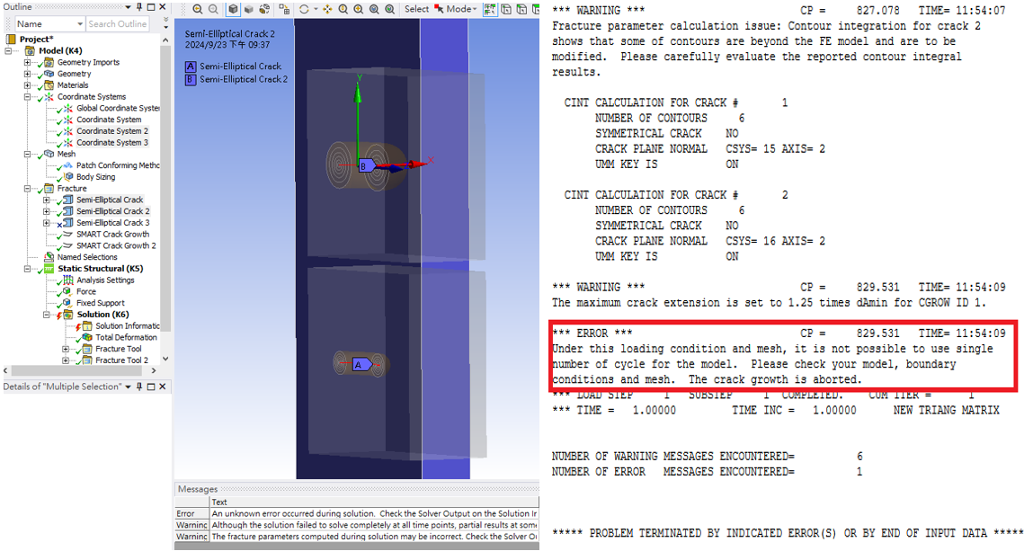
SubscriberHello everyone, I am doing research about double non-coplanar cracks growth with different depths. If the two cracks are far apart. crack growth can be established. However, if the two cracks are close to each other(about 5~10 mm). I will encounter this error problem(as shown in the picture).
There is no problem in different crack depths under static conditions, but it becomes unfeasible when switching to fatigue conditions.
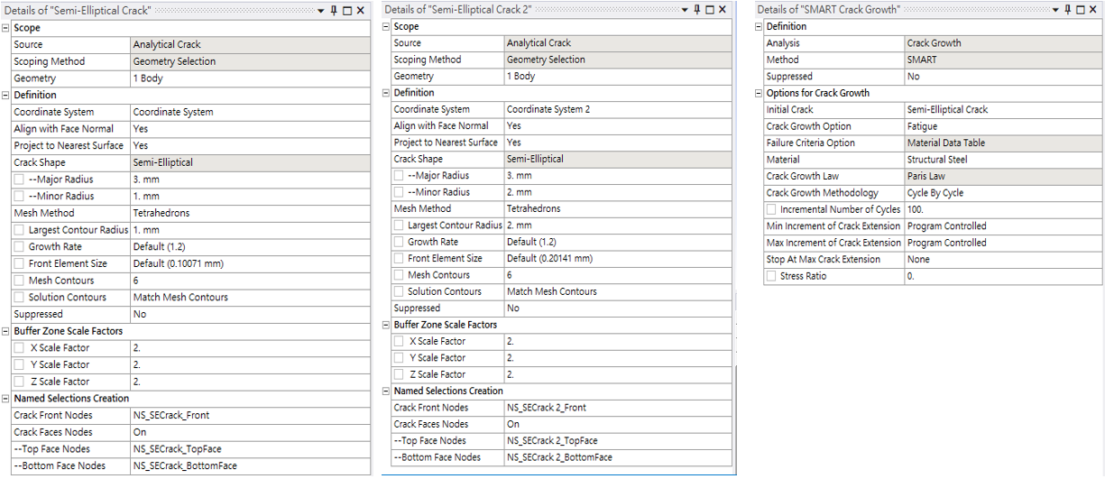
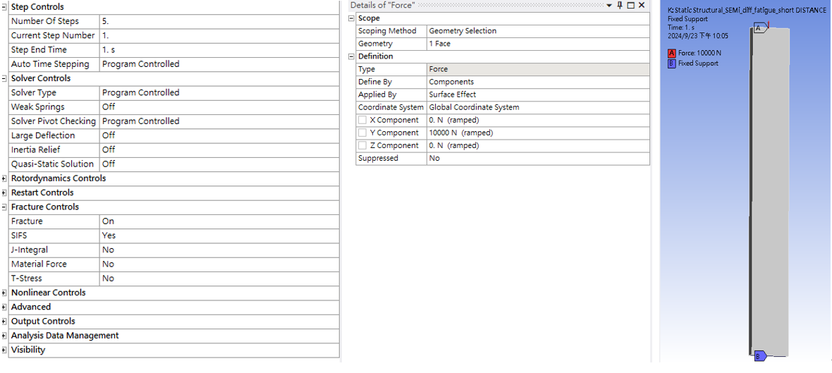
Here are some parameter settings
Crack1 Crack2 SMART crack growth
Boundary conditions
-
September 24, 2024 at 4:40 pm
David Weed
Ansys EmployeeHello,
When the crack extension increment, delta_a, is calculated using the cycle by cycle method, it is expected to be relatively close to the element size along the crack front (the default maximum delta_a increment, damax, is set to 1.5*element_size). If the calculated delta_a is greater than damax, then the program will automatically scale both delta_a and delta_N (these will be a new delta_a and delta_N values for the next sub step), to be closer to the damax value. (For reference see section 3.3.1.11. Specifying the Crack-Growth Increments in a Step in the MAPDL Fracture Analysis Guide)
Since the solver is reporting a single number of cycles in the error message, this may indicate that the program is significantly scaling down delta_a and delta_N due to the calculated delta_a value widely overshooting damax. The issue is that this doesn't adhere to the assumptions of stable fatigue crack growth, as mediated by the Paris' Law parameters, hence the message about aborting the crack growth portion of the solve.
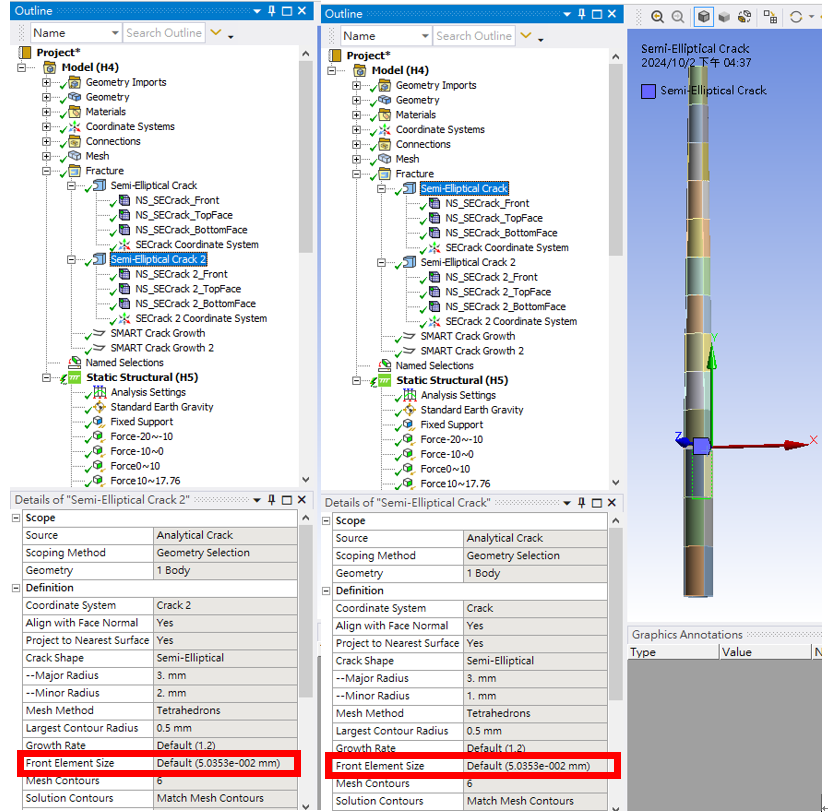
To achieve a more reasonable result, there are a number of inputs which can be adjusted such as adjusting the mesh size along the crack front, adjusting the damax parameter, and/or adjusting the boundary condition loading. To lend a bit more precision to your choice, consider doing a manual calculation of delta_a using the program-calculated SIF value without specifying crack growth. e.g., suppress the SMART crack growth object and run a simulation with your current loading. Take the max SIF value and use that to calculate delta_a at a given node using the following formula:
delta_a_at_node_i = delta_N*(delta_a/delta_N)_at_node_i
where delta_N = 100 cycles and (delta_a/delta_N)_at_node_i = C*delta_K^m (K can be taken from a given node along the crack front). This will reveal how close the initial calculated delta_a value is to damax (which can be calculated as 1.5*element_size along the crack front at node i). Based on this, you can adjust either of the aforementioned inputs and re-run the fatigue crack growth simulation to see if the calculation make more sense.
-
October 2, 2024 at 8:41 am
liuguanhong32
Subscriber
-
- You must be logged in to reply to this topic.


-
4683
-
1565
-
1386
-
1242
-
1021

© 2025 Copyright ANSYS, Inc. All rights reserved.


