TAGGED: interface, left-handed-faces, sliding-mesh
-
-
October 27, 2022 at 12:56 pm
Thodorisdm
SubscriberDear,Â
I have two cell zones. One is a cylindrical one and is rotating and the other one is the stationary domain.Â
I computed the origin and direction of rotational axis but when I preview the mesh motion after defining the interface in the mesh interfaces option, I can see that the rotating cell zone is not rotating as I indicate in the axis direction. Moreover, it creates at some points left handed faces because it intersects with the stationary domain cells.Â
I cannot really explain what goes wrong. I have two possible guesses: Either the rotation works only when axis has a direction of a main axis (x,y,z) or I should leave some gap between my cell zones so that the left-handed faces are not created at those points.Â
-
October 27, 2022 at 3:07 pm
Rob
Forum ModeratorI assume you have a sliding interface between the two zones, and that you have both the axis origin and direction set correctly?Â
-
October 27, 2022 at 3:09 pm
Thodorisdm
SubscriberYes. I have calculated the origin and direction of the axis of rotation from the CAD file and I have assigned the interfaces as well.Â
-
-
October 27, 2022 at 3:28 pm
Rob
Forum ModeratorPlease can you share a screen grab of the boundary condition part of the tree and interface panel?
-
October 27, 2022 at 4:13 pm
Thodorisdm
SubscriberI am not sure whether I included exaclty what you needed. If not, would you please elaborate more on the tree panel?
Cylinder inner--> the interface of the rotating zone. Cylinder outer--> the interface of the stationary zone which coincides in the beginning with cylinder inner. Cylinder top and bottom are the interfaces on the top and bottom of the cylindrical cell zone.Â
-
-
October 27, 2022 at 4:44 pm
Rob
Forum ModeratorThat'll do. The tree menu (left side) would show that you have interface zones: it's a common beginners error to think an interior is an interface. Those all look OK, my only concern is the precision of the axis definition. Depending on the overall scale I suspect you're off by a fraction, but that should just cause the moving zone to drift around and not effect the cell quality.Â
-
October 27, 2022 at 8:53 pm
Thodorisdm
SubscriberThank you for your reply. The precision of the axis definition is double checked. What else could I do to avoid these left handed? How can I monitor them and see where they are located so to increase the quality of the mesh at that location. Would this help?Â
-
-
October 28, 2022 at 9:50 am
Rob
Forum ModeratorLeft handed after a few time steps means the interface isn't working as there are cells being deformed at the boundary. It may be something you've (not) done, but could also be the newer methods in Fluent as you have several faces making up the interface zones.Â
Read  https://ansyshelp.ansys.com/account/Secured?returnurl=/Views/Secured/corp/v222/en/flu_ug/flu_ug_sec_grid_nonconform.html  then focus on Section 6.6.4. Once you've diabled the one-to-one pairing delete the non-conformal interfaces and recreate manually. You may need to reload the mesh as once it's twisted you can't do much with it.Â
-
October 28, 2022 at 1:00 pm
Thodorisdm
SubscriberThank you for you reply. I managed to define more accurately the origin of rotation and axis of rotation. I previewed the mesh motion for 50s and it appears one left handed face at 24 s. The cells in that location, however, are of a good quality. However, I dont think this will affect the solution that much so I can start running the simulation right?Â
Another observation : after 50 s the left handed faces are created more frequently (every 5 - 6 seconds). How would you explain this?Â
Finally, it is not feasible to open the above link. Can you specify the chapters you are refering to in the documentation?Â
-
-
October 28, 2022 at 1:32 pm
Rob
Forum ModeratorOpen Help via the solver, then click on the link. You just need a token for the system that the solver sorts.Â
-
October 28, 2022 at 1:39 pm
Thodorisdm
SubscriberGreat! Thank you. Could you also give an explanation of my observation? Why, although rotating (period is 12 seconds) I find 1 left handed face afte 24 seconds and then I find some after 50 seconds. I mean, the mesh is passing by that same location multiple times but not always left handed faces are created.Â
-
-
October 28, 2022 at 2:05 pm
Rob
Forum ModeratorI don't know without a detailed look at the case: which I can't do via a public platform. How well matched are the facet sizes on both sides of the interface? In theory nothing can twist on the mesh as it's sliding and not deforming.Â
-
October 28, 2022 at 3:03 pm
Thodorisdm
SubscriberThe interface is ovelapping 100%.
I will try to explain how I constructed it. In the beginning, both cell zones were one. Then I cut the cylindrical cell zone, keeping its outer body as the boundary of the stationary domain. Then for the cut cylindrical zone I modified the mesh size in its outer body so that I could create the non-conformal mesh in the interface. Therefore, the two interfaces coincide exactly, only difference is that in the cylindrical cell zone there are more cells.
I hope my explanation provided some clarity. An option would be to recontruct the rotating domain (cylindrical) to be slightly smaller than it is now, so that it doesnt touch the interface of the stationary domain, so no twisting will probably take place. Would you recommend that to me?
-
-
October 28, 2022 at 3:32 pm
Rob
Forum ModeratorWeird. And as you have the interface pairs it's not like you have the same face on both sides of the set up. Changing the rotating domain size isn't recommended as the gap should mean there's little/no overlap.Â
If you recreate the interface so you have many to many faces on each side? I assume the cylinder isn't distorted in any way? Why the odd tet region?
-
October 28, 2022 at 3:41 pm
Thodorisdm
SubscriberI am sorry but the interface I sent you is with identical number of faces in both interfaces. The cylinder is not distorted but what I am starting to suspect for the left handed faces is that the cylinder is not a perfect cylinder so while it moves in some points it penetrates with the stationary interface.Â
The interface consists of both structured and unstructured cells because the cylindrical interface is enclosing an archimedes screw and it wasnt possible to create a structured volume mesh in all locations inside the cylinder.
-
-
October 28, 2022 at 3:48 pm
Rob
Forum ModeratorIf the cylinder is eccentric it'll not give left handed faces as it'll just not overlap in places. Carefully check the outer edge of the screw aren't part of a different surface (or interface) as if they're in close proximity in the CAD you might have either mislabelled or have a CAD tolerance issue.Â
-
October 28, 2022 at 4:03 pm
-
-
October 28, 2022 at 4:39 pm
Rob
Forum ModeratorHow far are the blades from the interface? Turn off perspective on the views as it only confuses things!Â
-
October 28, 2022 at 4:42 pm
Thodorisdm
SubscriberThey are 2 mm far from the interface.
-
-
October 28, 2022 at 4:48 pm
Rob
Forum ModeratorAnd the cell size around there?
-
October 28, 2022 at 4:53 pm
Thodorisdm
SubscriberIf we take the 2mm as the k direction, the cells on that location have 5 mm on i and j directions.
-
-
October 29, 2022 at 1:46 pm
Thodorisdm
SubscriberI would like to give an example of the locations these left handed faces are created.Â
In the first picture you can see the poor element at the outer part of the interface (stationary domain). In the 3rd picture you can see the poor element at the inner part, right below of the location of the poor element in the outer part.Â
There is no corner, or sharp angle, I dont know what has gone wrong.Â
-
October 31, 2022 at 9:14 am
Rob
Forum ModeratorIt looks like something is twisting. How many rotating fluid zones are there? If you separate the stationary zone by region does anything happen (use report in that panel).Â
-
October 31, 2022 at 10:57 am
Thodorisdm
SubscriberThank you for your reply.Â
What do you mean by twisting? How can two cylindrical surfacesÂ
There is one rotating fluid cell zone which is the low part of the above images. The other fluid zone is the rest of the domain which is stationary.Â
I have a question, with regards to the separation by region. When clicking on report it produces the first window, I selected keep all interfaces and then I got the report depicted in the 2nd image. What exactly is meant in the output of the report?
-
October 31, 2022 at 11:12 am
Rob
Forum ModeratorThat's interesting. As you are picking one of the cell zones, and you only have two labelled I'd not expect any separation. Create an isosurface of mesh that cuts through the axis of the rotating part, make sure you select the rotating zone when you create it: that'll give you a plane through the rotating zone. Repeat, but pick the stationary zone. How do they look?
-
October 31, 2022 at 2:44 pm
Thodorisdm
SubscriberThank you for your reply. I chose for the iso surface the constant to be the interface overlap fraction.Â
In the first images you can see how it looks in the stationary and in the last images you can see the rotating cell zone. It seems that the cells in the interface are distorted (I cannot explain by what). One initial guess would be the fact that I have interface in the top and bottom of the cylinder instead of having an interface only in the body of the cylinder, would that be valid?Â
Stationary domain :Â
Â
Â
For the rotating domain:Â
-
October 31, 2022 at 3:22 pm
Rob
Forum ModeratorI'd use constant x, y or z and make sure no surfaces were picked. The intent is to see whether you've got any overlap or duplicate cells.Â
-
October 31, 2022 at 4:48 pm
-
October 31, 2022 at 5:05 pm
Rob
Forum ModeratorOther than some suspect jumps in cell size it looks OK from an interface point of view. Â
-
October 31, 2022 at 5:32 pm
Thodorisdm
SubscriberTherefore, what would your final suggestion be? I am considering the following 3 options:Â
- Reconstructing the cylinder with larger space between the screws and the interface.
- Using only usntructured cells in the interface.Â
- Exclude the bottom and top sides of the cylinder --> make them as wall so the interface will be only the body of the cylinder.
Any other suggestion would also be more than welcomed.Â
Â
Â
-
November 1, 2022 at 9:27 am
Rob
Forum ModeratorÂ
Save the case. In the domain tab delete the sliding volume, check the interface surface is continuous, and save with a new file name. Open the original case and delete the static zone, check the interface surface is continuous, and save with a new file name.
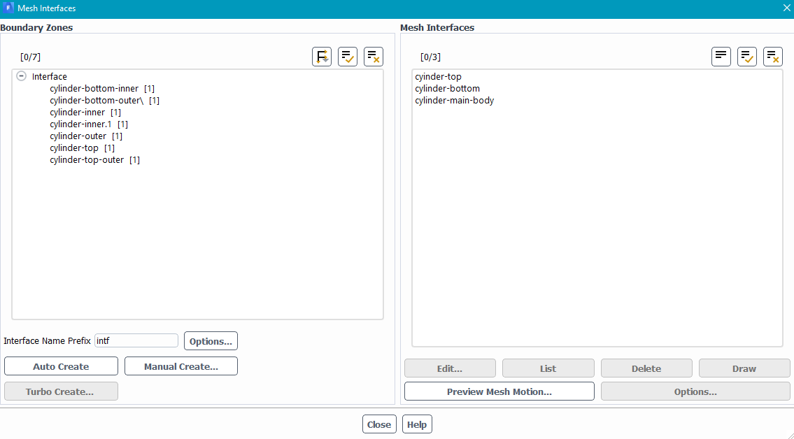
Open one or other of the new cases. Then append the other using the domains. Recreate the non-conformal having disabled the one-to-one setting.Â
Â
Of your suggestions:
1) That'll give a mismatch so whilst the mesh may not twist you'll not get any flow either.Â
2) Shouldn't make a difference to the interface but should fix the cell growth rate problems.Â
3) If it's sliding with mesh on the "other" side it needs to be interface. If the end coincides with the end of the domain wall is correct but remember to set the angular velocity as zero absolute.Â
Â
Â
-
November 1, 2022 at 10:03 am
-
November 1, 2022 at 11:11 am
Rob
Forum ModeratorIf you're deleting cell zones how are you retaining both inner and outer surfaces? The interface bc should be unique to each fluid zone.Â
-
November 1, 2022 at 11:19 am
Thodorisdm
SubscriberWhen I deleted the static zone, I only retained the cylinder inner, cylinder-bottom-inner, and cylinder top, which after they became wall bc.Â
When I deleted the rotating, I only retained the cylinder outer parts accordingly.Â
Then when I appended the stationary to the rotating, I had to make the above wall bc to interface and construct the interface again.Â
-
November 1, 2022 at 11:33 am
Rob
Forum ModeratorThere shouldn't be any way for the solver to turn cells inside out in that case: the sliding zones have to be separate given the changes.Â
-
November 1, 2022 at 11:37 am
Thodorisdm
SubscriberExcuse me, but I dont fully understand. The sliding zones are separate : cylinder inner parts belong to rotating cell zone while the cylinder outer parts belong to the static cell zone.Â
Could you please elaborate more?
Thank you in advance.
-
November 1, 2022 at 1:18 pm
Rob
Forum ModeratorAs each side of the interface pair is unique (inner and outer) and you have a non-conformal interface there should be no way the solver can twist the mesh. Hence, I'm not sure what's going on in your model without looking at the case, and I'm not able to do that from the Community.Â
-
November 1, 2022 at 2:07 pm
Thodorisdm
SubscriberIf I understand correctly, you imply that the solver cannot transform the interface surfaces to wall surfaces after deleting the other cell zone?Â
The only reason that the above happened, was because I had the non-conformal interface on. If I firstly delete the non-conformal interface then the surfaces in the non-deleted cell zone are still assigned as interface bc.Â
Is there another way to contact Ansys support?Â
-
November 1, 2022 at 2:12 pm
Rob
Forum ModeratorThe solver shouldn't be able to distort the mesh if the two sides of the interface are correctly assigned to the two fluid regions. As you've checked that, and deleted each side to confirm there is no connection I don't know why it's not working.Â
Your supervisor (ie a staff member) may be able to contact support depending on the licence status of your University.Â
-
- The topic ‘Sliding mesh-cell zone not rotating properly’ is closed to new replies.
-
4708
-
1565
-
1386
-
1242
-
1021
© 2026 Copyright ANSYS, Inc. All rights reserved.


