-
-
October 2, 2023 at 10:08 am
Joan Pons Llinares
SubscriberGood morning,
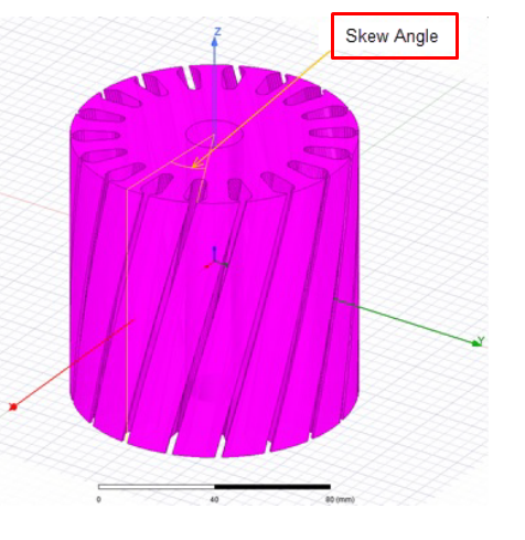
I have an induction motor that I am trying to model using Ansys Maxwell. My objective is to carry a 2D simulation that consider that the rotor bars are skewed.
From the manufacturer, we know that the bars are skwed 1.5 rotor slot pitch. Since the motor has 46 bars, this gives us an skewing angle of: 1.5*360/46 = 11.7391.
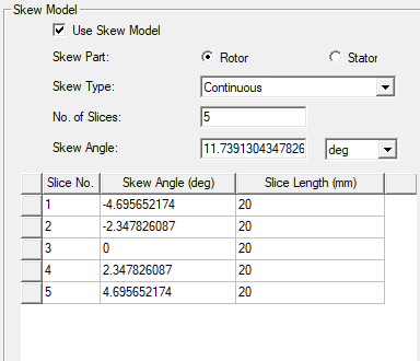
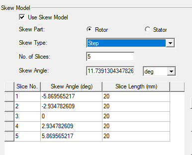
My question is, in order to reproduce this in Ansys, which of the following options should I used? Because I see differences between continuous and step. In continous the angle difference between first and fifth slice is 9.38, while in step the difference is the skewing angle I have introduced. Also, is 11.7391 the angle I must introduced?
Continuous
Stepped
-
October 2, 2023 at 5:56 pm
GLUO
Ansys EmployeeHello,
For the "Continuous" type, the skew angle (total) is measured at the center of each slices. The "Step" type is measured at the edge of each slices. You have to decide which type to choose based on how the 1.5 slot pitch is measured.
GL
-
October 2, 2023 at 6:34 pm
Joan Pons Llinares
Subscriber
-
-
October 2, 2023 at 6:43 pm
GLUO
Ansys EmployeeHi Jorge,
Yes, that is the correct angle to put for continuous case.
Although it is coninuous skew, 2D model has to model it as multiple slices The 9.38 is the difference between the center of the first and the last slice.
GL
-
October 3, 2023 at 7:36 am
Joan Pons Llinares
SubscriberThank you very much for your kind reply.
All crear.
Jorge
-
-
- The topic ‘Skewing angle in Maxwell 2D for an induction motor’ is closed to new replies.


- Three-Phase Voltage Imbalances in dual stator electric generator
- Link the Circuit to 3D Terminals
- Magnetic Dipole moment calculation
- Integration lines or U Axis Line for circular and rectangular ports
- Core Loss in ANSYS MAXWELL Eddy Current solution
- exporting and importing my Netlist for my external circuit
- Error of Metal Fraction in Icepak Classic.
- The unit of theta in Is*sin(2*pi*fre*Time+theta-2*pi/3)
- Two way coupling for Maxwell and thermal problem
- simplorer-maxwell

-
4618
-
1530
-
1386
-
1210
-
1021

© 2025 Copyright ANSYS, Inc. All rights reserved.


