
TAGGED: mechanical-apdl, rotating-machinery
-
-
December 31, 2021 at 10:11 am
Mihir_Rayganga
SubscriberHello,
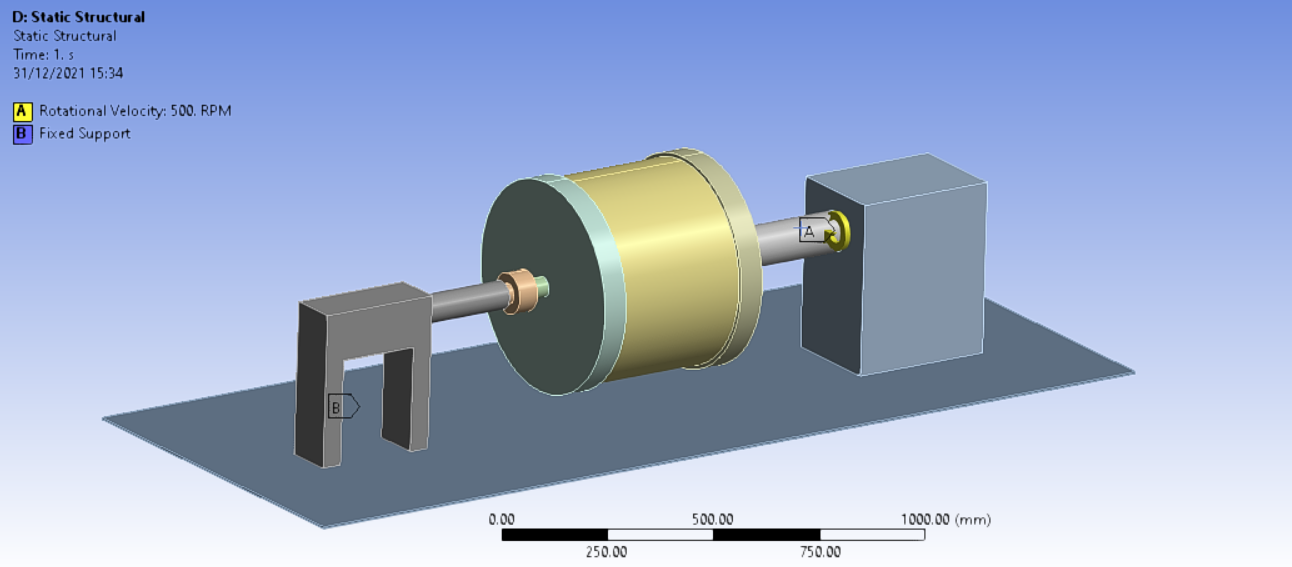
I am trying to set up a static stimulation for my rotating cylinder supported by 2 shafts. I am relatively new to FEA so wanted someone knowledgeable to check if my simulation setup is correct as per my requirement or not. Attaching photos for reference:
December 31, 2021 at 1:27 pmpeteroznewman
SubscriberMany beginners using a Rotational Velocity load mistakenly believe that the simulation will rotate the parts. That is not what happens. The load just applies a radial acceleration to each element that is a function of the radius of that element from the axis and the angular velocity you specify.
You have a rotor in the center of the shaft, with bearings at each end of the shaft. You are interested in the stresses in the rotor spinning at 500 RPM. For this first analysis, you could leave out the supporting structure at each end of the shaft. Just include the parts that rotate. Now the Rotational Velocity load can be applied to all the bodies.
In a Static Structural analysis, the parts must be connected to ground in all six rigid body degrees of freedom. A common approach is to cut the shaft at the center of the first bearing at each end. On each cut face, create a Remote Displacement. The Remote Displacement at the motor end will have a 0 for X, Y, Z and Rotation Y and the two others Free. The Remote Displacement at the support end will have X and Z set to 0 and all others Free.
The Revolute Joint you created is not a good way to create a revolute joint. If you use this in the future, pick two small surfaces near each other, don't pick the entire body.
Viewing 1 reply thread- The topic ‘Simulation setup for a rotating cylinder’ is closed to new replies.
Innovation Space Trending discussions
- LPBF Simulation of dissimilar materials in ANSYS mechanical (Thermal Transient)
- Convergence error in modal analysis
- APDL, memory, solid
- Meaning of the error
- How to model a bimodular material in Mechanical
- Simulate a fan on the end of shaft
- Real Life Example of a non-symmetric eigenvalue problem
- Nonlinear load cases combinations
- How can the results of Pressures and Motions for all elements be obtained?
- Contact stiffness too big
Top Contributors
-
peteroznewman
 4167
4167 -
scabo
 1487
1487 -
Dennis Chen
 1338
1338 -
javat33489
 1188
1188 -
Shyam Prasad V Atri
1021
Top Rated Tags
© 2025 Copyright ANSYS, Inc. All rights reserved.
Ansys does not support the usage of unauthorized Ansys software. Please visit www.ansys.com to obtain an official distribution.
-


The Ansys Learning Forum is a public forum. You are prohibited from providing (i) information that is confidential to You, your employer, or any third party, (ii) Personal Data or individually identifiable health information, (iii) any information that is U.S. Government Classified, Controlled Unclassified Information, International Traffic in Arms Regulators (ITAR) or Export Administration Regulators (EAR) controlled or otherwise have been determined by the United States Government or by a foreign government to require protection against unauthorized disclosure for reasons of national security, or (iv) topics or information restricted by the People's Republic of China data protection and privacy laws.


