TAGGED: udf
-
-
November 28, 2023 at 4:14 am
Bruce Zhou
SubscriberHello, everybody!
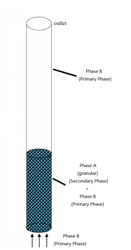
I am now having trouble simulating a 3-D multiphase flow problem including chemical reaction, whose simulation domain is shown in Fig. 1 below.
Eulerian multiphase model was selected for the simulation and 3 Eulerian phases (Phase A-secondary granular phase, Phase B-primary liquid phase, Phase C-secondary gas phase) were involved. In material setting, Phase A is a mixture with 3 components and is handled as fluid in calculation. The chemical reaction is described as
aA=bB+cC
Actually, it is a component of Phase A that is involved in the reaction. The chemical reaction starts as the temperature of Phase A (symbolized as Ta) exceeds a certain value (symbolized as Treac).
As for boundary and initial condition, as shown in Fig. 1, the bottom of the domain is set as mass flow inlet and the top of the domain is set as pressure outlet (gravity acceleration is considered in the problem). Initially, the entire domain is filled with Phase A and Phase B with different temperature (Ta
Treac). Meanwhile, Phase B with temperature of Tb comes into the domain through inlet boundary at a certain velocity. As is mentioned in my previous post, I am now learning about UDF and I am now trying to simulate the above problem in 2 different approaches. One approach is to adopt the Heterogeneous reaction model in Fluent (version 19.2), and the other approach is to add source terms to the conservation equation via DEFINE_SOURCE macro.
In defining source terms, I referred to the theory guide of Fluent and defined the following sources (details are omitted)
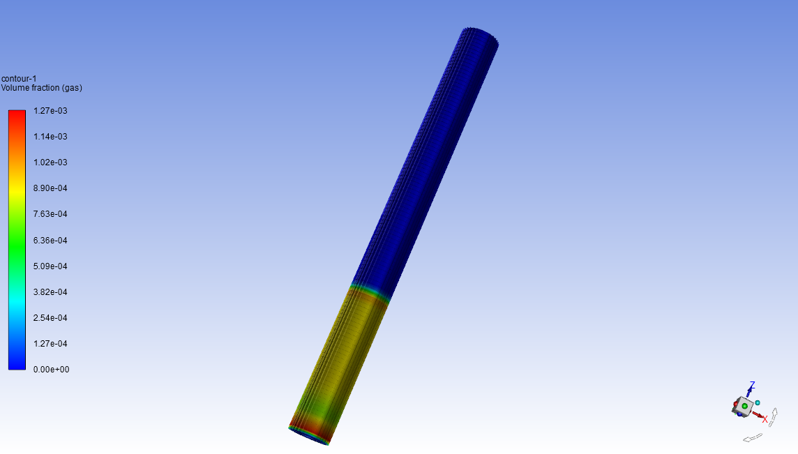
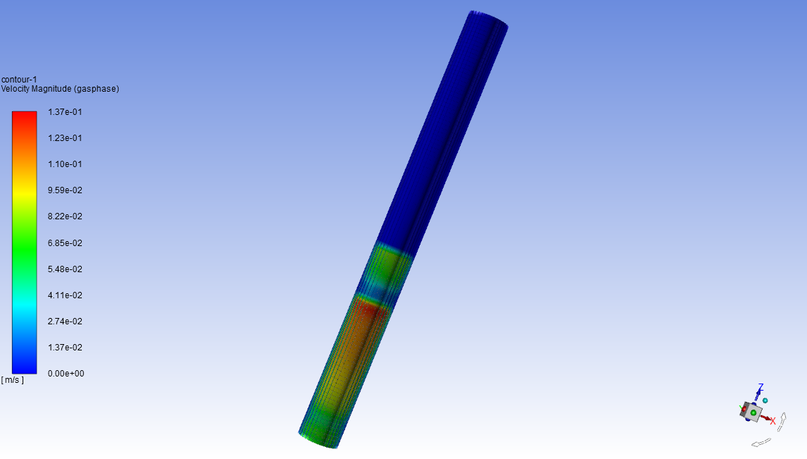
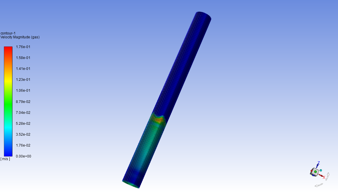
However, the simulation results obtained via the two approaches differs significantly. The simulated gas phase volumetric fraction contour and gas phase velocity contour is shown below
Gas phase (Phase C) volumetric fraction (UDF)
Gas phase (Phase C) volume fraction (reaction model)
Gas phase (Phase C) velocity (UDF)
Gas phase (Phase C) velocity (reaction model)
The above results are at t = 1 s. The difference in velocity is particularly significant, which I believe causing the difference in other parameters.
Before starting the calculation, I went through the two simulation cases for several times to ensure the consistency in parameter setting (material propery, model selection, phase interaction, boundary and initial condition, etc.). The two cases are with the same mesh and time step.
The difference shown above have confused me for quite a long period. I am quite sure that there is no coding miss in my UDF, and I am wondering if my understanding on the numerical method is insufficient. I cannot figure out where the above difference come from. Is there anything incorrect or missing in my UDF settings? Please, help!!!!
-
November 28, 2023 at 3:52 pm
Rob
Forum ModeratorYou may want to look up iso-surfaces to plot contours on (for example) the y or x =0 plane.
If energy has an effect on reaction rate, and you're slightly off at (for example) 0.001s would you expect the result to drift significantly from the Fluent model?
-
November 29, 2023 at 1:03 am
Bruce Zhou
SubscriberThanks! I would go to check my case setting.
-
-
- The topic ‘Simulation results inconsistent’ is closed to new replies.


-
4763
-
1565
-
1386
-
1242
-
1021

© 2026 Copyright ANSYS, Inc. All rights reserved.


