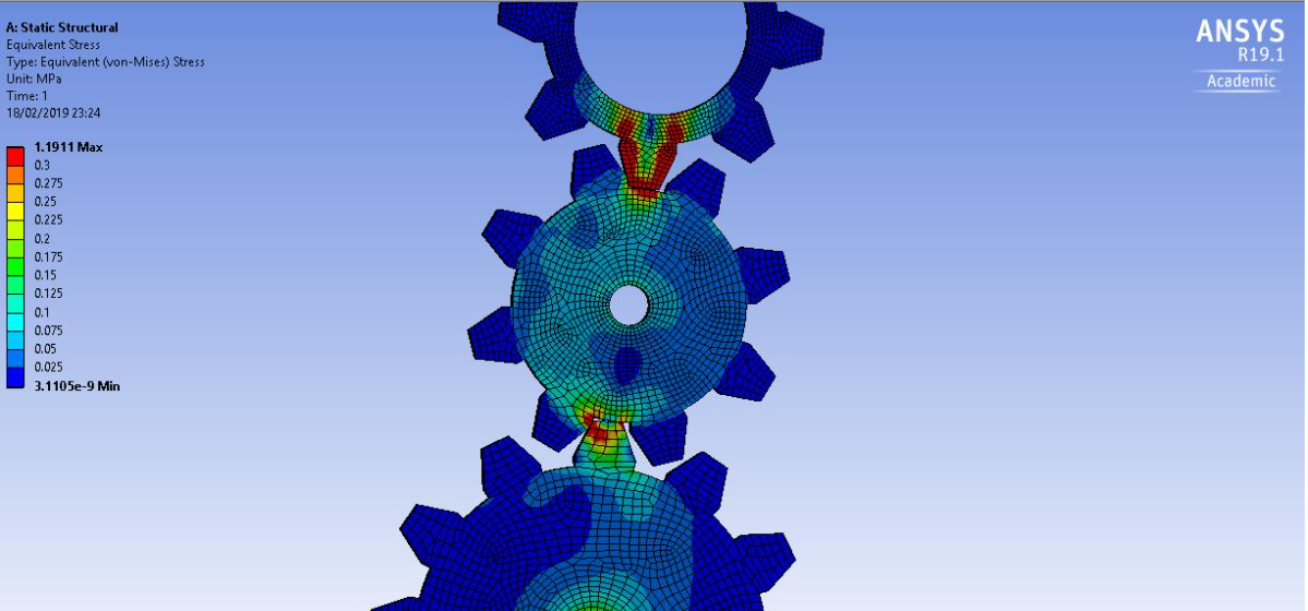
-
-
October 12, 2021 at 7:02 am
dhebynanda97
SubscriberHello guys, can anyone help me to solve my problem in spiral bevel gear simulation, I have got the results but the results are not in accordance with the theory, it could be that I am wrong in the input on ansys, please help me, guys, if it works, I will give you a reward, thank you,
CP : 085835560536
October 13, 2021 at 11:09 pmpeteroznewman
SubscriberWhat theory did you use and what did it show?
What results did you get from Ansys?
October 14, 2021 at 2:57 amdhebynanda97
SubscriberCan we discuss with WA bro??
October 14, 2021 at 4:11 ampeteroznewman
SubscriberNo bro, we discuss it right here.
October 14, 2021 at 4:16 amdhebynanda97
Subscriberokay bro, so this is related to my final project problem, I solved a problem related to the broken teeth in the spiral bevel gear, here I see the tension in the gear which will later be related to the result of broken teeth in the gear, can you help me bro??
October 15, 2021 at 12:30 pmpeteroznewman
SubscriberOkay, since you have solved a problem related to the broken teeth in the spiral bevel gear, reply with details how you solved that problem. What were the results?
October 15, 2021 at 5:18 pmdhebynanda97
SubscriberI'm looking for the maximum stress that occurs in the gear teeth, but the results I get are not in accordance with the formula I used as validation, am I wrong in inputting what is on ansys or what, that's my problem bro, can you help me bro?
October 15, 2021 at 6:03 pmpeteroznewman
SubscriberIt's hard to help you if you don't provide any details.
Show the formula you used as validation and the result you got.
Show the model you used and the results you got.
October 19, 2021 at 7:07 amdhebynanda97
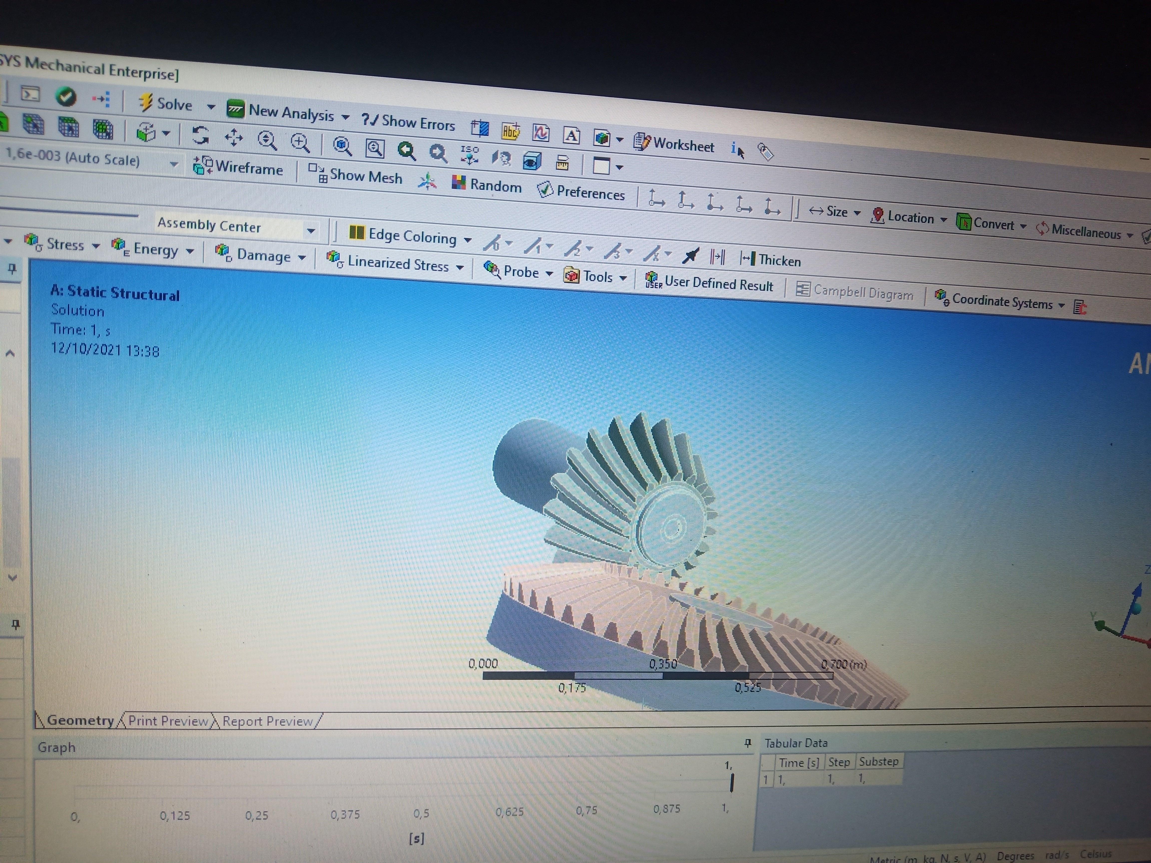
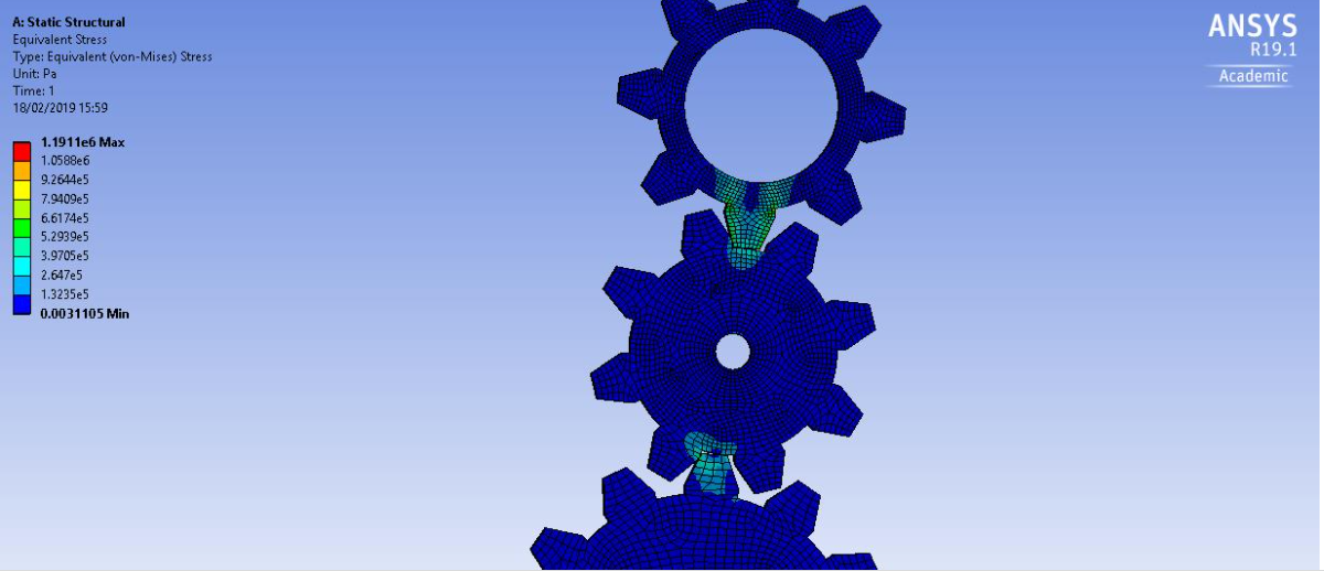
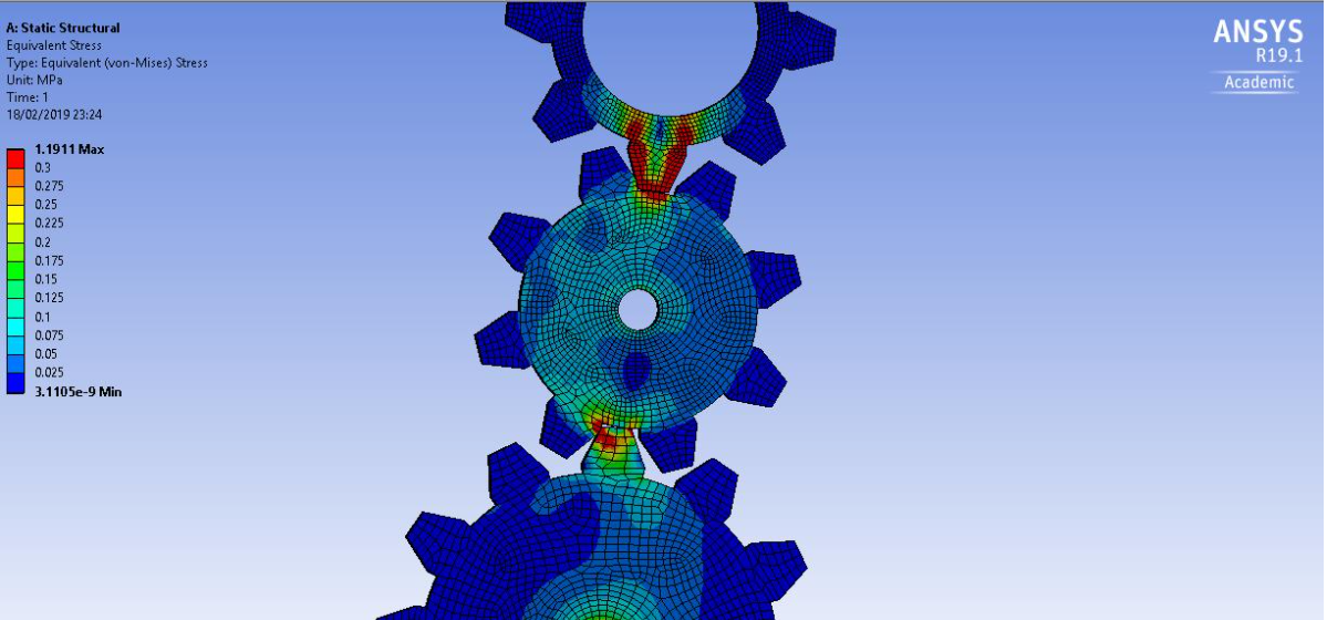
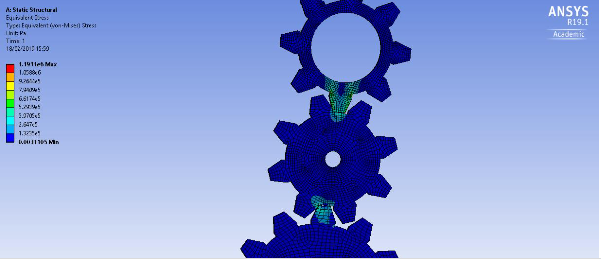
Subscribersorry bro, I just opened the discussion forum bro, here I try to detail my simulation, please help me bro, thank you,
October 20, 2021 at 5:25 pmpeteroznewman
SubscriberThanks for the photos bro.
Here is a Google Search of this site with 38 results for the words: gear tooth stress https://www.google.com/search?q=site%3Aforum.ansys.com+peteroznewman+gear+tooth+stress
Please read through at least the first two pages of links. Note that some discussions are more than one webpage long and you need to click the 2 to get to page 2 of the discussion.
 See how they don't model a complete 360 degree piece of the gear, but maybe only a 30 degree slice. Pay attention to the size of the elements, see how small they are at the contact point. This is where you need to go to get a better agreement between your model and the hand calculation.
October 29, 2021 at 4:12 amdhebynanda97
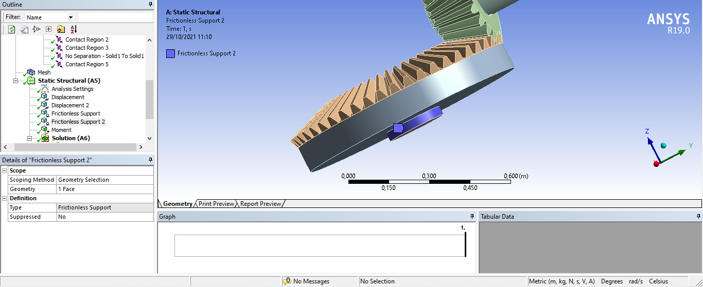
Subscriberhello bro,, thank you for the solution you gave bro, after I saw and understood the solution you gave, I didn't find the same thing related to the problem I was experiencing, now I want to ask about the boundary conditions and contacts that I input in my simulation whether is it right or what bro?? thanks bro,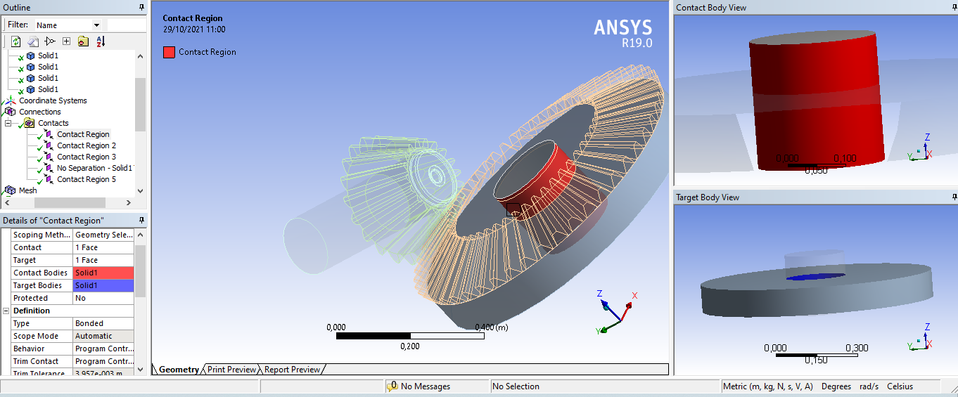
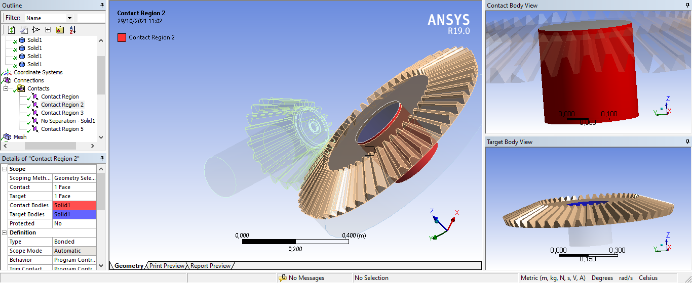

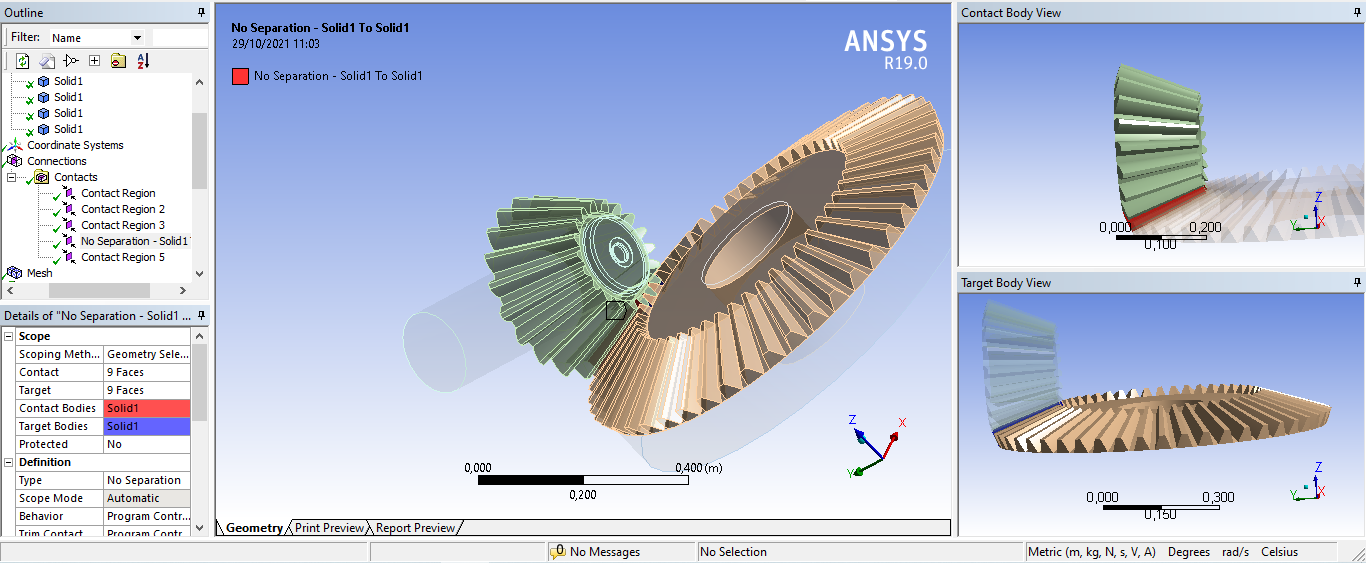
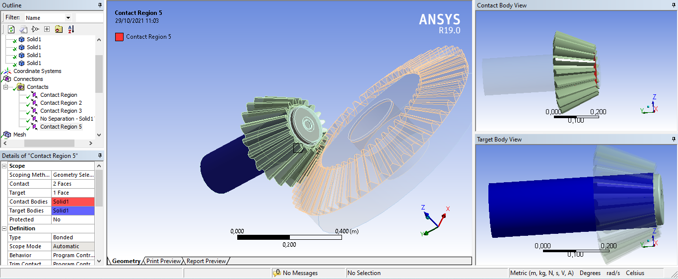
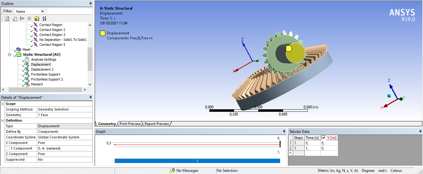
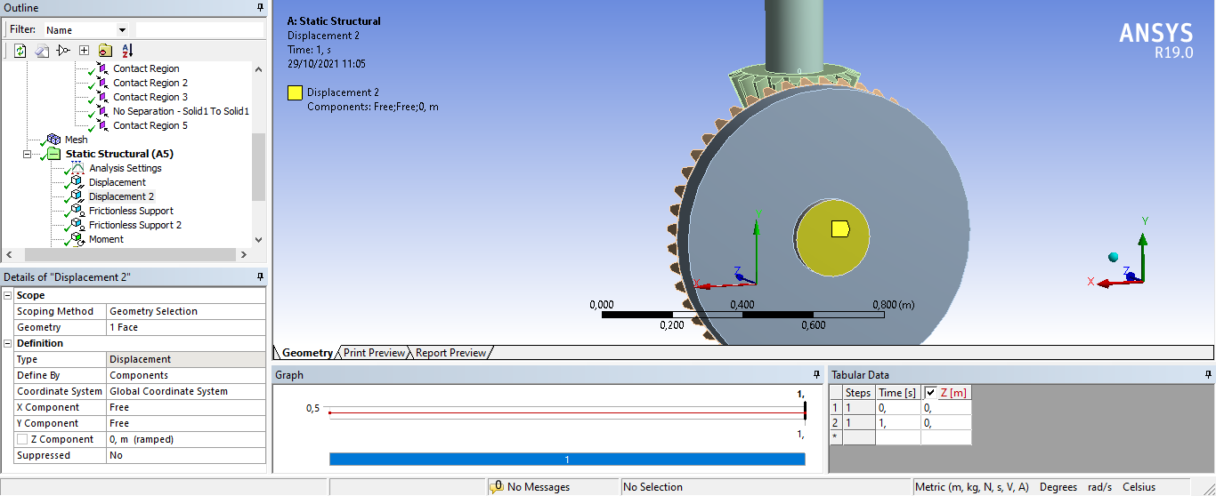
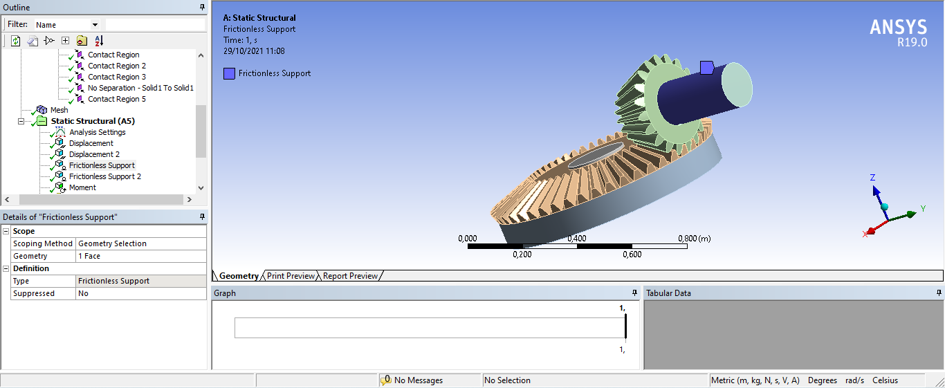

October 29, 2021 at 4:37 amOctober 30, 2021 at 9:01 pmpeteroznewman
SubscriberDon't model a complete 360 degree piece of the gear, but maybe only a 30 degree slice. Don't use any contacts. In CAD, unite the disk with the teeth, unite the shaft with the teeth. Then you will have only 2 bodies to mesh. Pay attention to the size of the elements, see how small they are at the contact point.
November 3, 2021 at 3:49 amViewing 13 reply threads- The topic ‘Simulation of spiral bevel gear’ is closed to new replies.
Innovation SpaceTrending discussionsTop Contributors-
4628
-
1535
-
1386
-
1215
-
1021
Top Rated Tags© 2025 Copyright ANSYS, Inc. All rights reserved.
Ansys does not support the usage of unauthorized Ansys software. Please visit www.ansys.com to obtain an official distribution.
-
The Ansys Learning Forum is a public forum. You are prohibited from providing (i) information that is confidential to You, your employer, or any third party, (ii) Personal Data or individually identifiable health information, (iii) any information that is U.S. Government Classified, Controlled Unclassified Information, International Traffic in Arms Regulators (ITAR) or Export Administration Regulators (EAR) controlled or otherwise have been determined by the United States Government or by a foreign government to require protection against unauthorized disclosure for reasons of national security, or (iv) topics or information restricted by the People's Republic of China data protection and privacy laws.

