-
-
November 5, 2024 at 4:04 pm
msyf
Subscriber
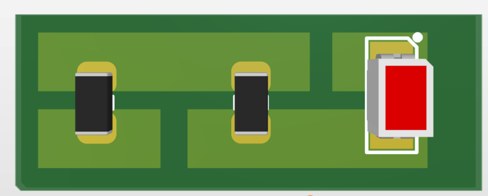
I am attempting a DC IR analysis using Ansys SIwave where I have multiple stages of resistors. Therefore, I have created a simple PCB for evaluation purposes. In the circuit, I have a voltage source, multiple resistors in series until it reaches an LED. For simplicity terms, I have created a dumbed down version of the setup.
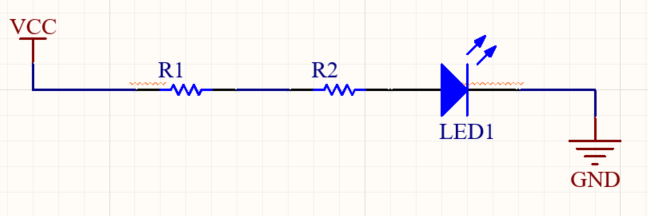
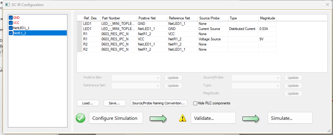
I have set the voltage source on R1 and the LED as a current source.
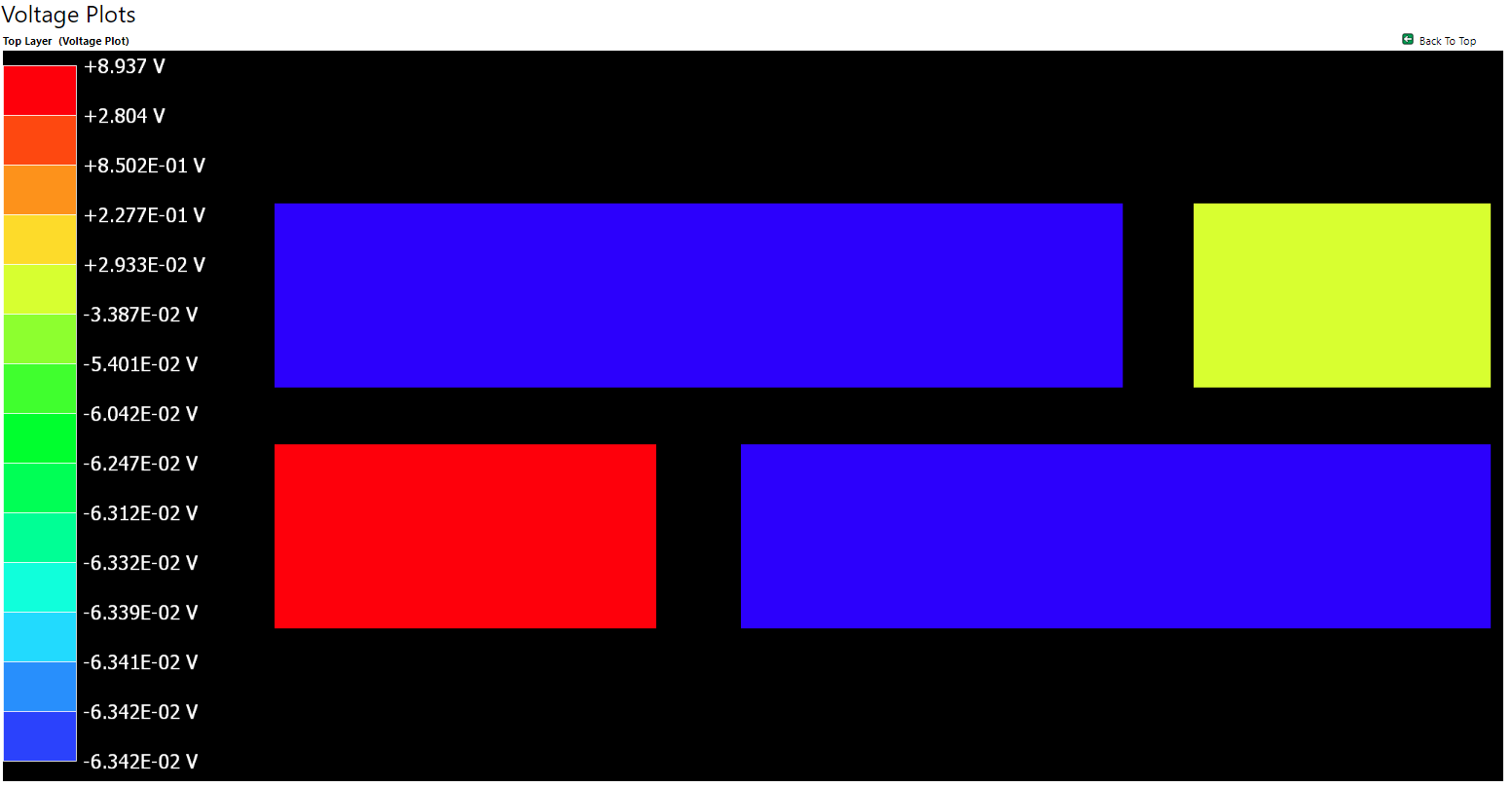
I am not able to simulate successfully the correct voltage levels across different the resistors.
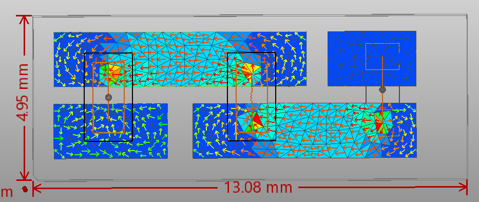
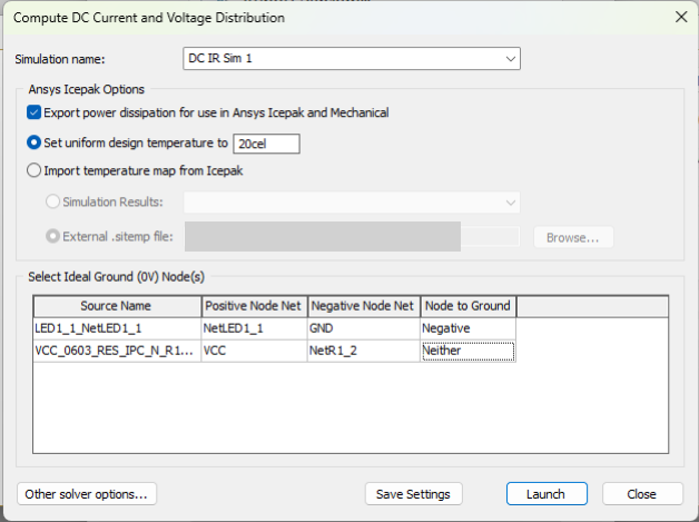
I am attaching the set configurations and the obtained results.
Can someone kindly guide me on the proper way to set this up?
-
November 7, 2024 at 11:15 am
Mrinmoy Bharadwaj
Ansys EmployeeKindly correct the set-up for correct results.
1. Your voltage source must be connected between VCC and GND (not NetR1_2). Both voltage and current source should have the same reference net.2. Select the "negative" for the voltage source under "Node to ground".
-
November 7, 2024 at 1:22 pm
matthew.sultana
SubscriberThanks for your reply.
-
-
- You must be logged in to reply to this topic.
- Three-Phase Voltage Imbalances in dual stator electric generator
- Link the Circuit to 3D Terminals
- Magnetic Dipole moment calculation
- Core Loss in ANSYS MAXWELL Eddy Current solution
- Error of Metal Fraction in Icepak Classic.
- The unit of theta in Is*sin(2*pi*fre*Time+theta-2*pi/3)
- simplorer-maxwell
-
4673
-
1565
-
1386
-
1231
-
1021
© 2025 Copyright ANSYS, Inc. All rights reserved.


