
-
-
February 24, 2021 at 7:42 am
yappyap
SubscriberHi all!
Here is my current model:
It is a brace with 6 cylinders in place to mimic screw attachments as seen in the following picture.
February 24, 2021 at 7:48 amSubscriberI have attached my file here and would appreciate any help. Thank you.nFebruary 25, 2021 at 6:30 am1shan
Ansys Employee,nLooking at the picture it looks like a leg brace, with tension cables which provide grip for attachment. You have added a contact between screws and the brace but you have not fixed the brace itself. In reality it is the contact between the leg and brace which prevents it from moving right? Unless you provide some king of constraint to the brace itself surface, it will cause rigid body motion errors. Also, the cylinders look too small and are not the object of interest (i assume). These would cause meshing difficulties, so you could delete them and add forces directly to 'hole' edges. Unfortunately ANSYS staff are not permitted to download attachments but feel free to attach images for description.nRegards,nIshan.nFebruary 25, 2021 at 9:38 amSubscriberHello Array,nThis is a body brace and unfortunately we do not have the patient's body model to attach as the constraint.nThe cylinders are just to mimic the screws. We would like to analyze if the forces acting on the straps (and therefore the screws) would cause any failure on the brace when used in the long run. Is it still realistic to just apply a force on the 'Hole' edges?nIn addition, I CADed out an M4 by 5 screw on the brace last night to replace the cylinders. However, i cant seem to create a hole on the surface of the brace. I couldn't use the hole option in spaceclaim for whatever reason??nThus, I drew out a screw and duplicated it. n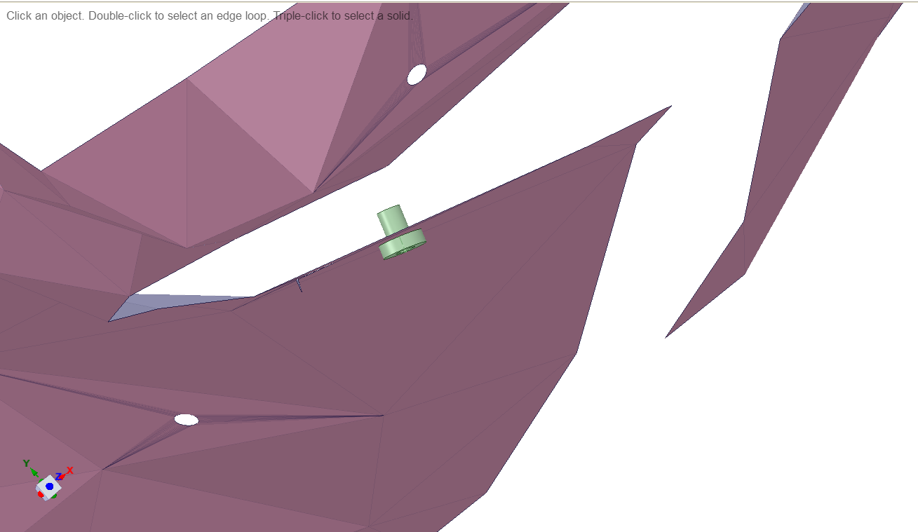 I used 1 of it to subtract from the brace, expecting to get a hole out of it. However, since it was a surface brace with triangulations, I had to delete some triangles that appear after the subtraction. I do not know why it only appears on one side of the brace and not the other.n
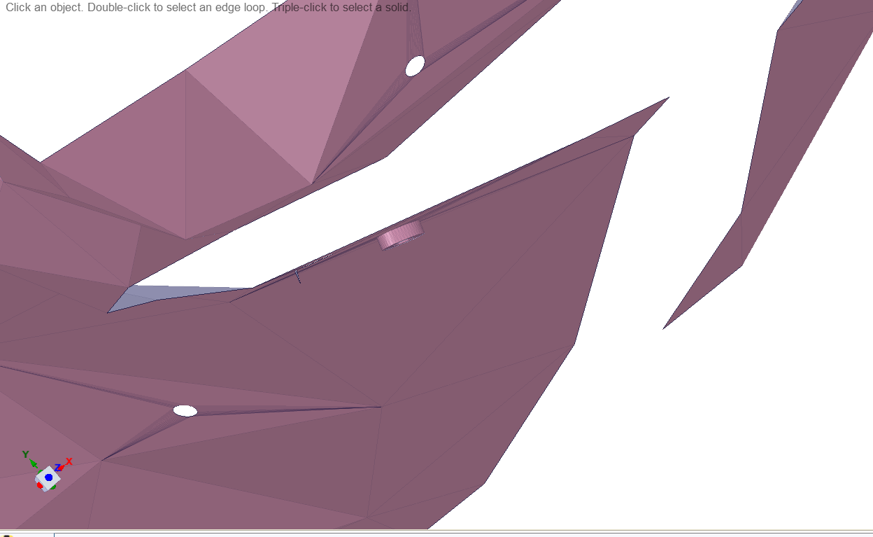
 But even after deleting, the existing triangles merged with the circle to produce something like this:n
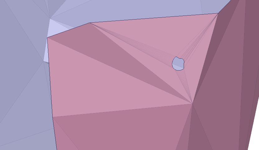 n
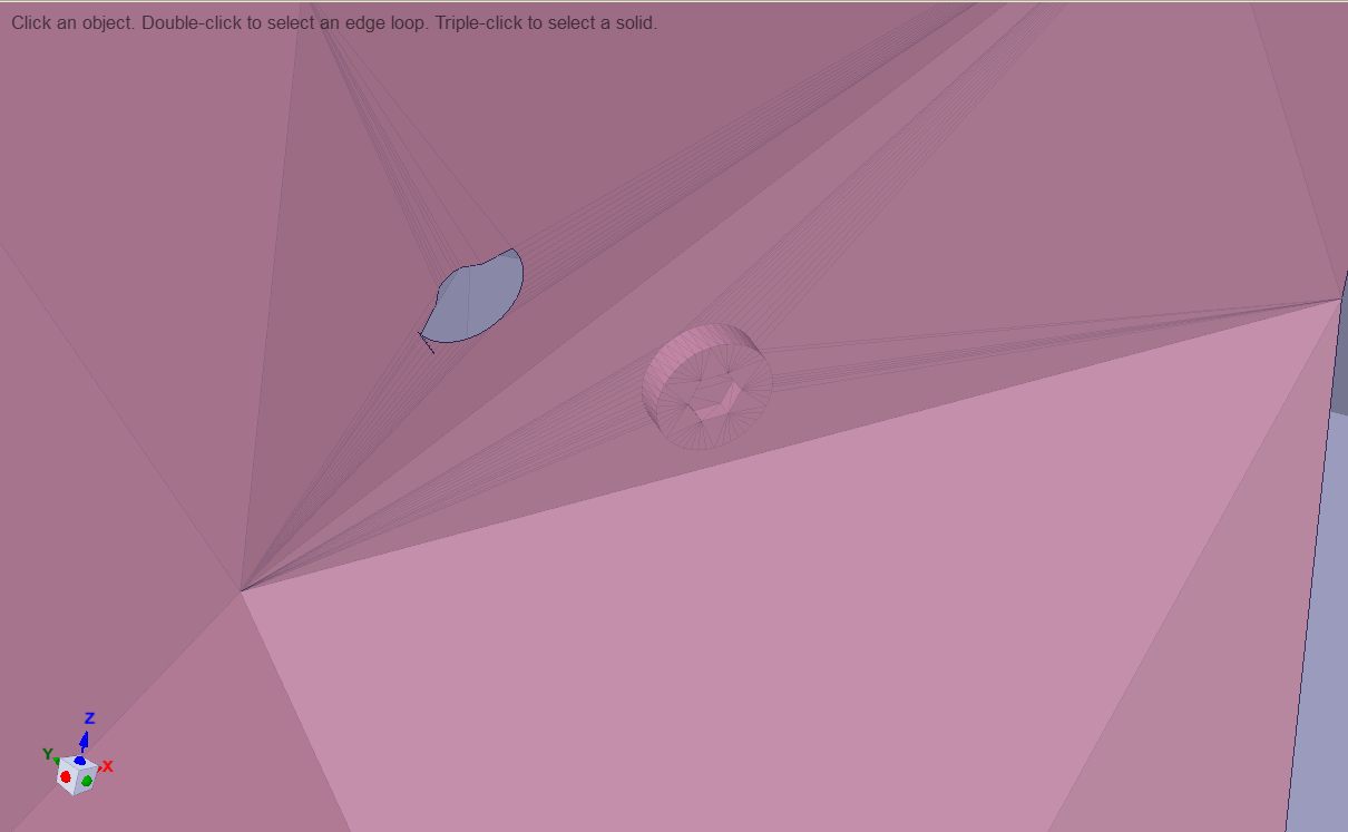
n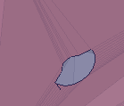 However, some other circles look perfectly shaped like this:n
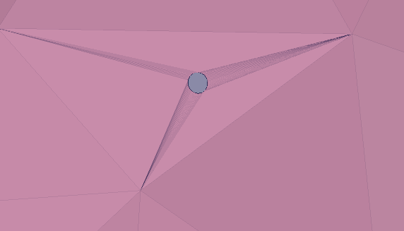 nnHow can i fix this?.Thank you.n
February 26, 2021 at 7:04 amAnsys Employee,nYou could add a plane in space claim (normal to axis of the screw), draw a circle on it and use the pull option to remove material and create a hole in the brace. To constrain the brace what you could do is add a cylindrical support at 3 holes (edges) and apply forces to the remaining holes. If the solver still gives you a rigid body motion error add cylindrical joint to one more hole (4 in total). Let me know if this works.nRegards,nIshan.nMarch 11, 2021 at 3:15 pmSubscriberHi Array,nYour previous comment mentioned to add forces directly to 'hole' edges. I removed the cylinders entirely and tried to add forces directly to the edges like you suggested. The same unconstrained error appears.nIs there an email i can share my file with you? I'm at my wits end as it has been 2+ weeks and the same error keeps appearing.nI just wish to apply forces on the holes to replicate the forces acting by the straps.nMarch 12, 2021 at 4:55 amAnsys Employee,nCould you add an image which clearly shows the support used at each holes and the forces you have added? Have you checked the mesh, whether it is following the edges across the holes? in the 2nd and 3rd image I see a bolt head merged with a surface. That doesn't look right. Could you create a clean geometry with just the brace and holes. It would also help if you do a normal modal analysis to check if the constraints are adequate and there is no rigid body motion. Unfortunately, we are not allowed to share our emails.nRegards,nIshan.nMarch 12, 2021 at 8:38 amSubscribershould i be using fixed supports on the holes? i tried to use remote displacements on the left holes to have more control of the DOFs, then applied a remote force on the right side to hopefully get an action-reaction force. It didnt work. I then used Fixed Supports on the left holes and applied force on one side. It didnt work too.nShould my remote points be Deformable or Rigid? I am using rigid now.nI have reduced the size of my mesh around the holes using body and edge sizing:n
nnHow can i fix this?.Thank you.n
February 26, 2021 at 7:04 amAnsys Employee,nYou could add a plane in space claim (normal to axis of the screw), draw a circle on it and use the pull option to remove material and create a hole in the brace. To constrain the brace what you could do is add a cylindrical support at 3 holes (edges) and apply forces to the remaining holes. If the solver still gives you a rigid body motion error add cylindrical joint to one more hole (4 in total). Let me know if this works.nRegards,nIshan.nMarch 11, 2021 at 3:15 pmSubscriberHi Array,nYour previous comment mentioned to add forces directly to 'hole' edges. I removed the cylinders entirely and tried to add forces directly to the edges like you suggested. The same unconstrained error appears.nIs there an email i can share my file with you? I'm at my wits end as it has been 2+ weeks and the same error keeps appearing.nI just wish to apply forces on the holes to replicate the forces acting by the straps.nMarch 12, 2021 at 4:55 amAnsys Employee,nCould you add an image which clearly shows the support used at each holes and the forces you have added? Have you checked the mesh, whether it is following the edges across the holes? in the 2nd and 3rd image I see a bolt head merged with a surface. That doesn't look right. Could you create a clean geometry with just the brace and holes. It would also help if you do a normal modal analysis to check if the constraints are adequate and there is no rigid body motion. Unfortunately, we are not allowed to share our emails.nRegards,nIshan.nMarch 12, 2021 at 8:38 amSubscribershould i be using fixed supports on the holes? i tried to use remote displacements on the left holes to have more control of the DOFs, then applied a remote force on the right side to hopefully get an action-reaction force. It didnt work. I then used Fixed Supports on the left holes and applied force on one side. It didnt work too.nShould my remote points be Deformable or Rigid? I am using rigid now.nI have reduced the size of my mesh around the holes using body and edge sizing:n n
n n
March 12, 2021 at 4:34 pmAnsys EmployeeHelloArray,nThe distorted elements near the holes might be creating the problem (the mesh is bad around the hole). Use shared topology to get rid of the small thin surface edges near the holes. Also use fixed support at first, and when the error is resolved use remote displacement. You could check this for using shared topologyhttps://www.youtube.com/watch?v=4JhDn0V26l0.nRegards,IshannViewing 8 reply threads
n
March 12, 2021 at 4:34 pmAnsys EmployeeHelloArray,nThe distorted elements near the holes might be creating the problem (the mesh is bad around the hole). Use shared topology to get rid of the small thin surface edges near the holes. Also use fixed support at first, and when the error is resolved use remote displacement. You could check this for using shared topologyhttps://www.youtube.com/watch?v=4JhDn0V26l0.nRegards,IshannViewing 8 reply threads- The topic ‘Simulation Error with Insufficient supports’ is closed to new replies.
Innovation Space Trending discussions
- LPBF Simulation of dissimilar materials in ANSYS mechanical (Thermal Transient)
- Real Life Example of a non-symmetric eigenvalue problem
- How can the results of Pressures and Motions for all elements be obtained?
- Contact stiffness too big
- Test post on Forum – LLM response – SC
- 13-Node Pyramid Element Shape Function
- Element Birth and Death
- Python-Script to Export all Children of a Solution Tree
- Which equations and in what form are valid for defining excitations?
Top Contributors
-
peteroznewman
 4577
4577 -
scabo
 1494
1494 -
Dennis Chen
 1386
1386 -
javat33489
 1209
1209 -
Shyam Prasad V Atri
1021
Top Rated Tags
© 2025 Copyright ANSYS, Inc. All rights reserved.
Ansys does not support the usage of unauthorized Ansys software. Please visit www.ansys.com to obtain an official distribution.
-


The Ansys Learning Forum is a public forum. You are prohibited from providing (i) information that is confidential to You, your employer, or any third party, (ii) Personal Data or individually identifiable health information, (iii) any information that is U.S. Government Classified, Controlled Unclassified Information, International Traffic in Arms Regulators (ITAR) or Export Administration Regulators (EAR) controlled or otherwise have been determined by the United States Government or by a foreign government to require protection against unauthorized disclosure for reasons of national security, or (iv) topics or information restricted by the People's Republic of China data protection and privacy laws.


