-
-
October 12, 2024 at 12:33 pm
edwardwflms
Subscriberim trying to simulate a surface acoustic wave resonator by Ansys 2023R1 in coupling harmonic and coupling static.Although i can get the solution,it seems to be wrong comparing to the answer of the same model in Comsol.I doubt the mistake may happen in the aspect listed below.
First,i use the element type 226 for both piezoelectric material and the electrode.I tried to use solid 186for the electrode instead,but someting wrong happend when i set the phisycal region.
Secondly. In comsol i have set a electric boundary conditon,which the surface charge density of the piezoelectric part is always zero.But i can find anywhere to set the same boundary condition instead.
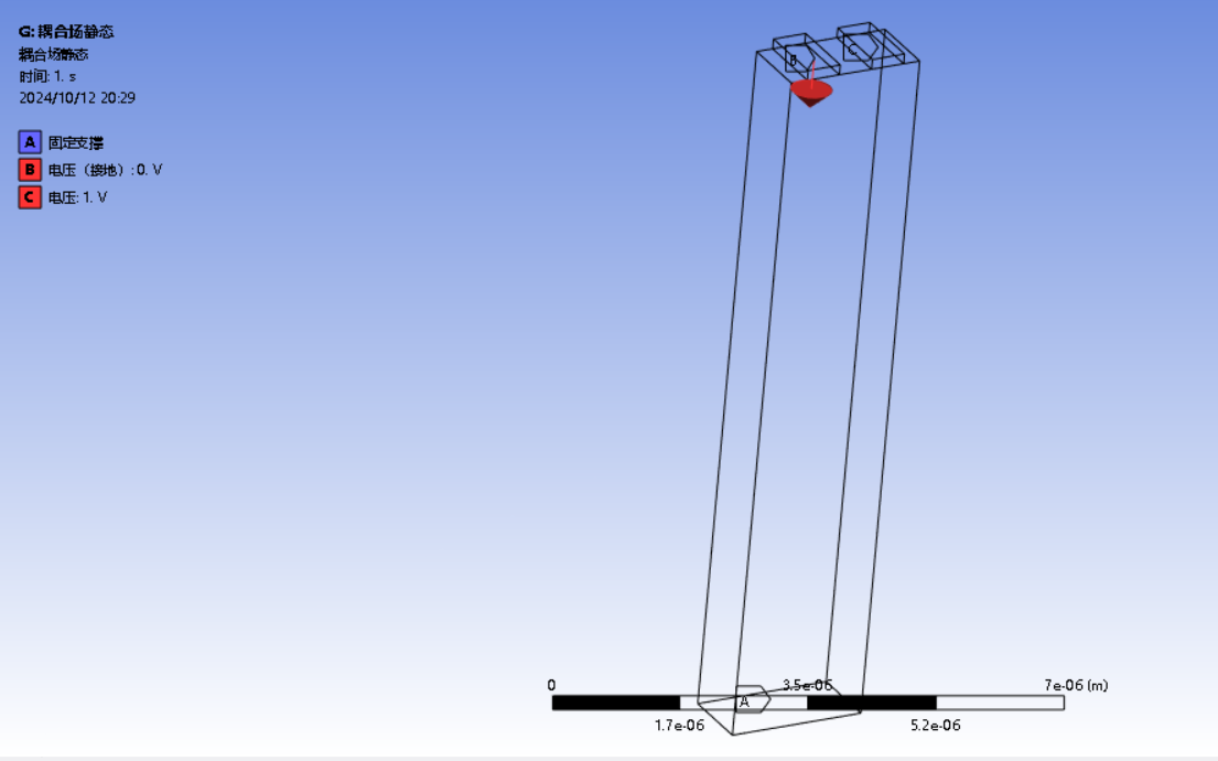
this is the model i made,for those who dont understand chinese A is the fixed support B is grounding voltage C is the input voltage which set to 1V.
Willingly find someone who can teach me how to fix my model.
i also found an example which can meet what i need can
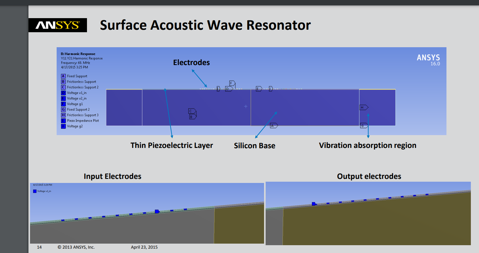
does anybody know how to reproduction the same model
-
October 16, 2024 at 8:33 pm
wrbulat
Ansys EmployeeHi,
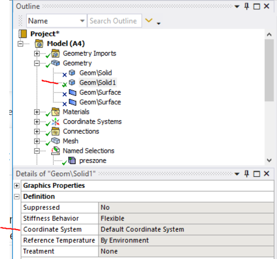
Be sure to apply periodic boundary conditions in your ANSYS model that are consistent with those applied in the COMSOL model (if any). Also be sure the direction of polarization of the piezo materials is consistent with that defined in the COMSOL model. In 3D piezo models, our piezo and anisotropic elastic matrices are usually defined in such a way that polarization is in the z direction. Assuming this to be the case, define a coordinate system with its z direction aligned with the desired direction of polarization direction in the piezo body in the physical device, and specify that coordinate system in the Coordinate System field in the piezo body details:
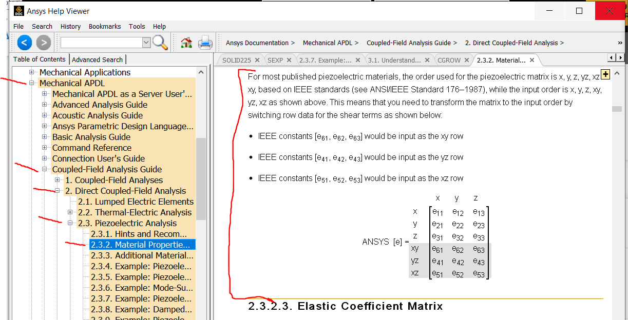
If you manually defined the piezo and anisotropic matrices yourself, you may have entered the data in the order consistent with the convention used by IEEE. The convention used in ANSYS differs from this as explained in the Help:
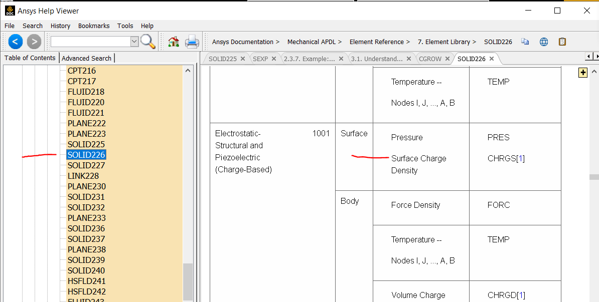
The electric charge on a free surface with no voltage constraints, no coupling on the VOLT DOF, and no enforced charge density should be zero - it is naturally occuring. I suppose you could use a command object to define, using the SF commmand, a zero charge density on a surface:
but that shouldn't change the calculated results from those you would get if you didn't do so.
I would suggest making a single part out of all the bodies in your model, and apply voltage boundary conditions on the piezo body surfaces that are interfaces with the electrode bodies. You should then be able to assign the electrodes to a structural physics region (they only add a little mass and structural stiffness to the system).
I hope this helps you,
Bill
-
December 2, 2024 at 1:21 pm
mesquius
SubscriberHi Bill,
I'm also interested in simulating acoustic wave resonatorts (SAW adn BAW) with Ansys. We are considering moving our simulation capabilities to Ansys for that matter, but we can't find any documentation or example for it (while there are many for other softwares like Comsol). Do you have any material on this topic? not a full 3D model, but a 2D cross section to compute the resonator response over frequency for example.
Marc
-
- You must be logged in to reply to this topic.


-
4673
-
1565
-
1386
-
1236
-
1021

© 2025 Copyright ANSYS, Inc. All rights reserved.

