-
-
October 2, 2024 at 8:40 pm
hasan.mustafa.moayad
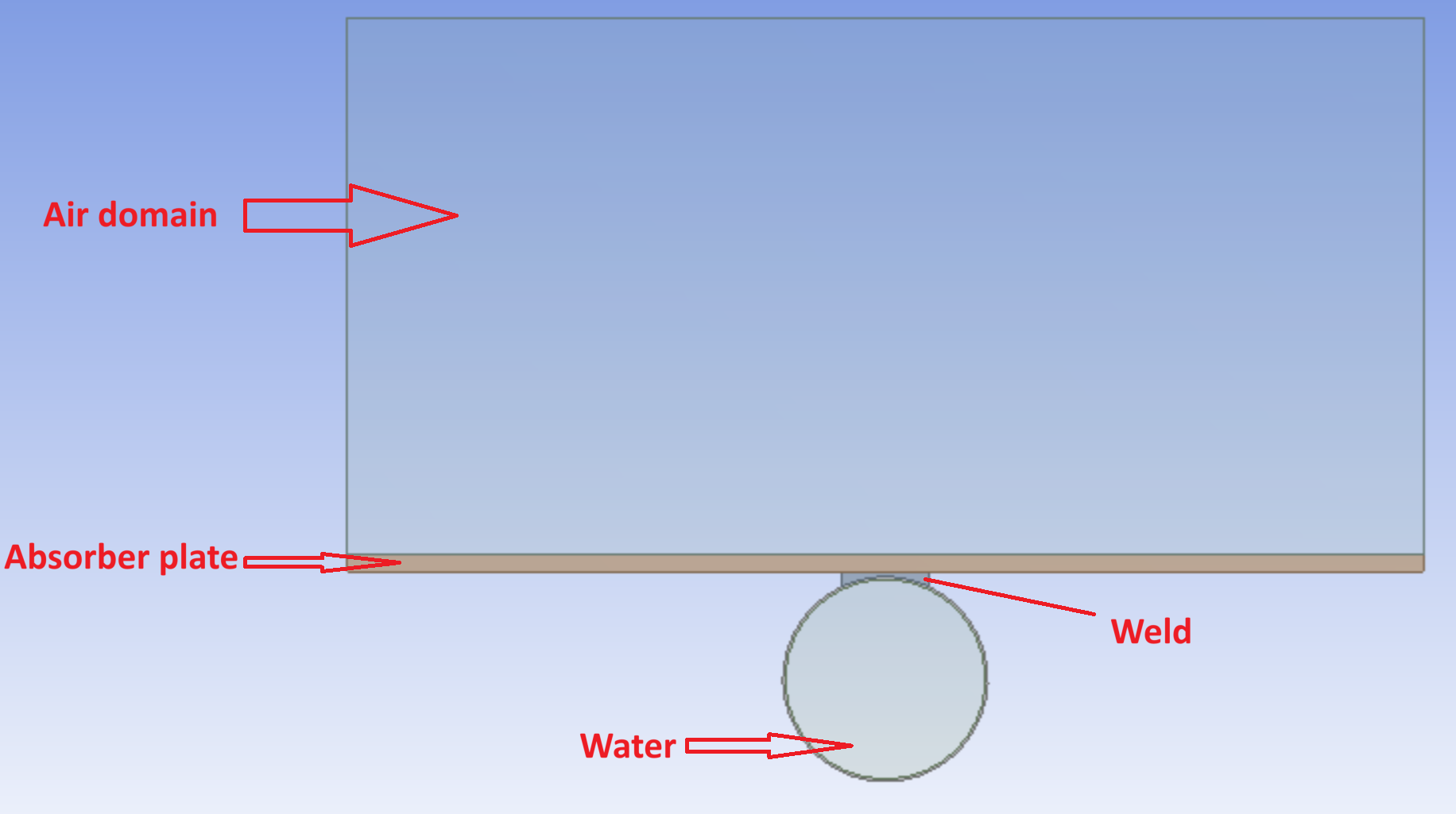
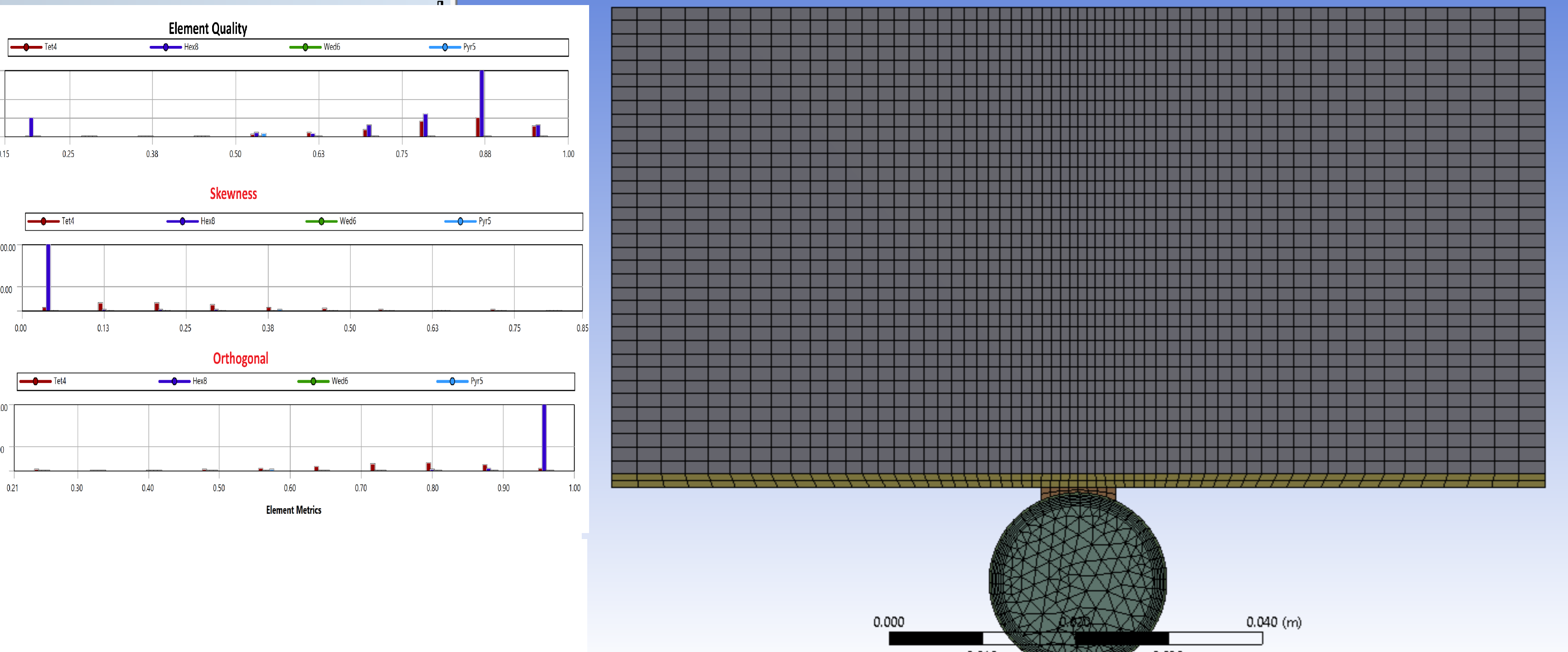
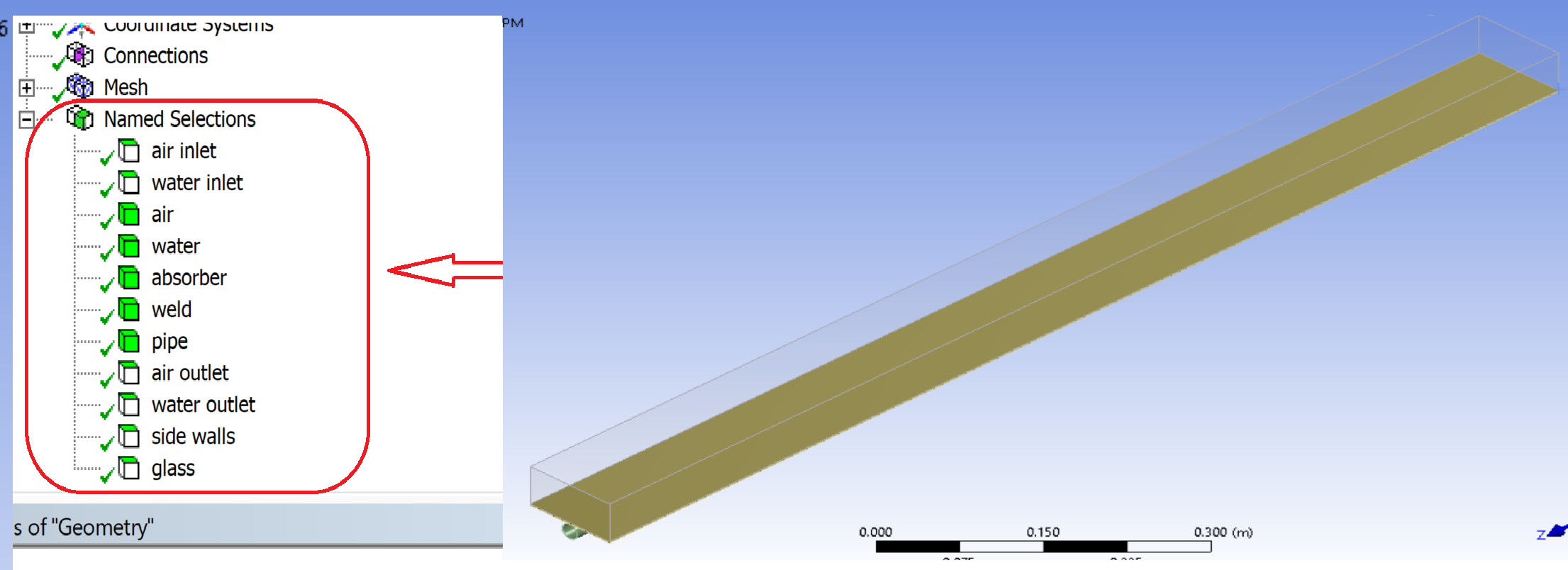
SubscriberHello, I'm simulating a dual-purpose solar collector which is used to heat both air and water simultaneously. I'm using Ansys Fluent for this simulation. To reduce the computation time, I draw a small geometry for this collector which consists of four domains (Air, Water, Absorber, and Weld). In design modeler I shared the topology then I proceeded to mesh (see image 1).
 In mesh, the element, skewness, and orthogonal qualities seem good, aren't they? (see image 2).
  Then, I named the bodies and surfaces as illustrated in the image (3).
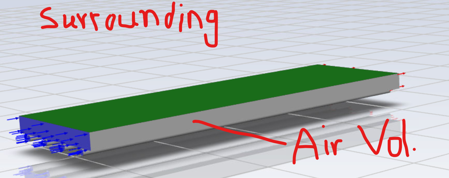
  The named surface (glass) is the top surface of the air domain which represents the collector's cover. This cover transfers heat with surroundings by convection, how does Ansys fluent deal with the surroundings (I mean the space outside my geometry)? because I have convection B.C. on the top of the air volume (green colored as in image 4), I put both the convection coefficient and free stream temperature. So, will the convection be between the green-colored surface and the surroundings? or between the green surface and the air volume (this is my first question)?
  In the setup,
 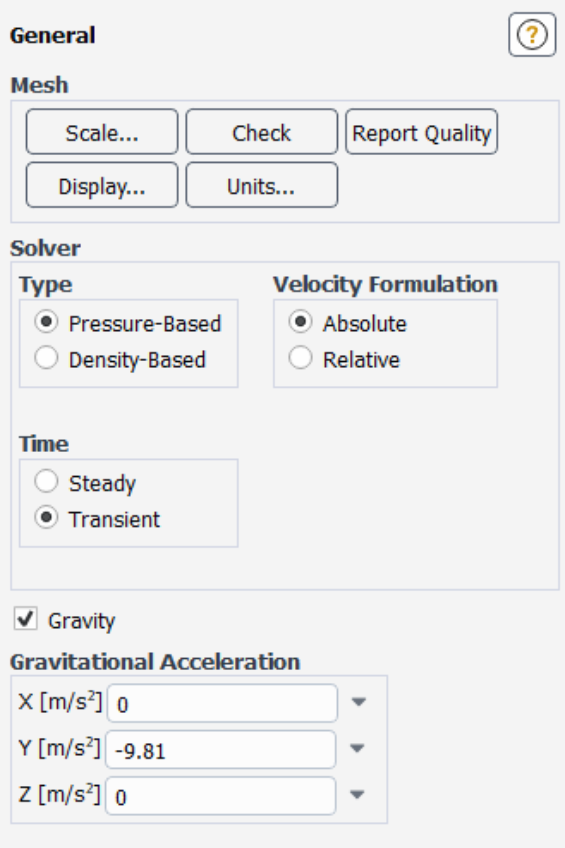 I activated the energy model with a laminar flow (because my case is laminar). I chose materials (air, water-liquid, steel for absorber, copper for weld and pipe, and I defined a new material which is glass that covers the collector). Then, I applied these materials to the 4 domains in cell zone conditions (except glass because it is a surface, not a body). In Boundary conditions, I entered the mass flow rate and temperature for inlet air and inlet water, for the outlet I chose a pressure outlet.
 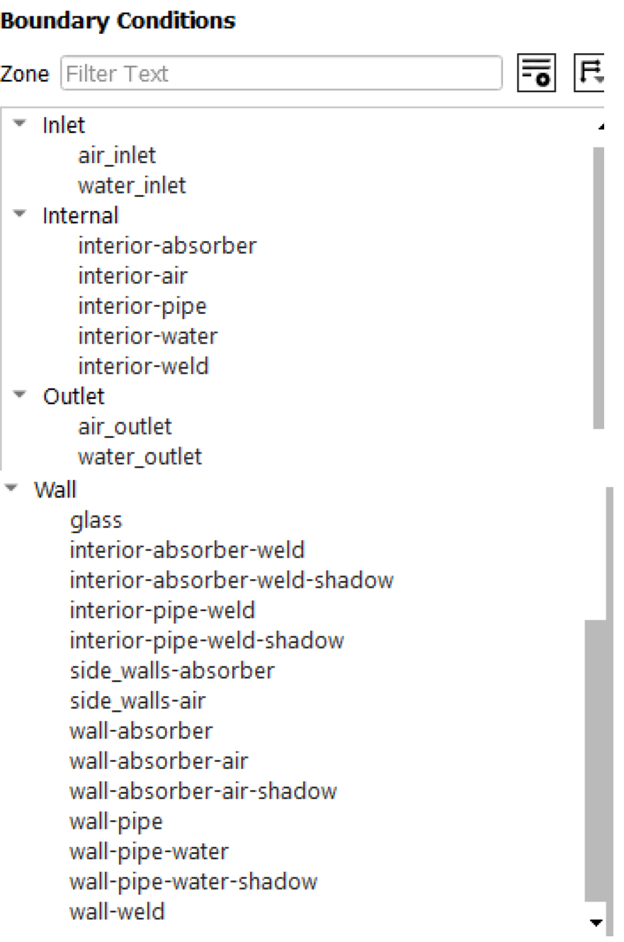 The other B.Cs are: 1) glass: it is the top surface of the air domain and its material is "glass" with convection thermal condition.
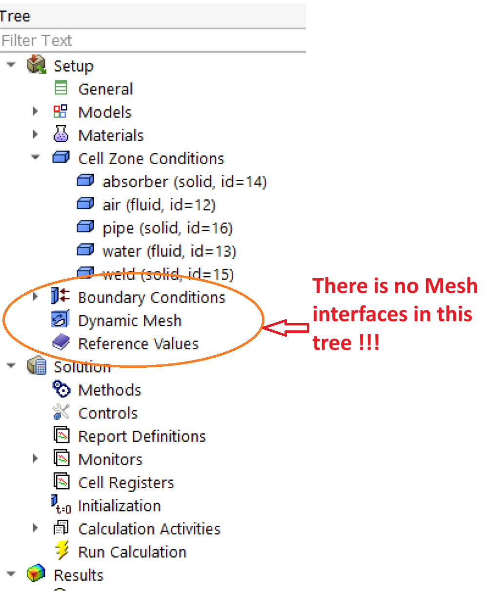
 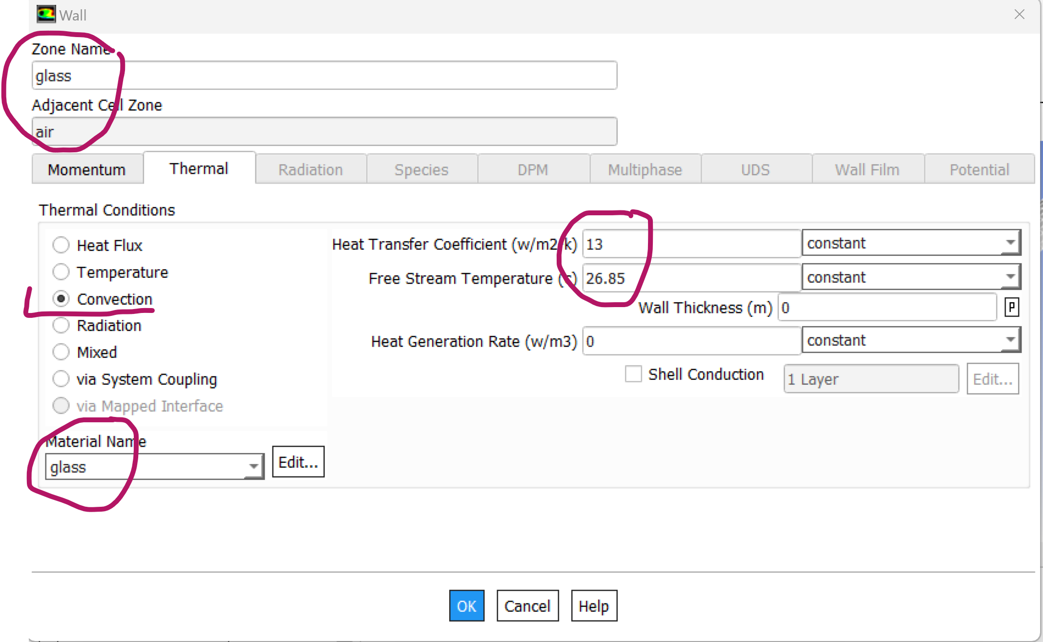 2) interior-absorber-weld: which is the interface between the absorber and weld domains, it is thermally coupled with steel as a material for it. 3)interior-pipe-weld: it is the interface between the pipe and weld domains, it is also thermally coupled with copper material. 4) side_walls-absorber: it represents the left and right sides of the collector which are attached to the absorber, steel is the material, these walls are considered isolated surfaces so I chose zero heat flux for thermal conditions. 5) side_walls-air: represents the left and right sides of the air domain, also isolated surfaces, I chose Aluminum as material for them and again zero heat flux for thermal conditions. 6)wall-absorber: represents the bottom, front, and back surfaces of the absorber domain, steel material, zero heat flux. 7) wall-absorber-air: represents the upper surface of the absorber domain where I'm applying a heat flux of 633 W/m2. 8) wall-pipe: represents the bottom, front, and back surfaces of the pipe domain. cooper material and zero heat flux. 9)wall-pipe-water: represents the interface between water and pipe domain, cooper material, zero heat flux ( because I assumed that there is an insulation material beneath the pipe). 10) wall-weld: represents the bottom, front, and back surfaces of the weld domain.cooper material and zero heat flux. I noticed there is no " Mesh Interface " in the outline tree.
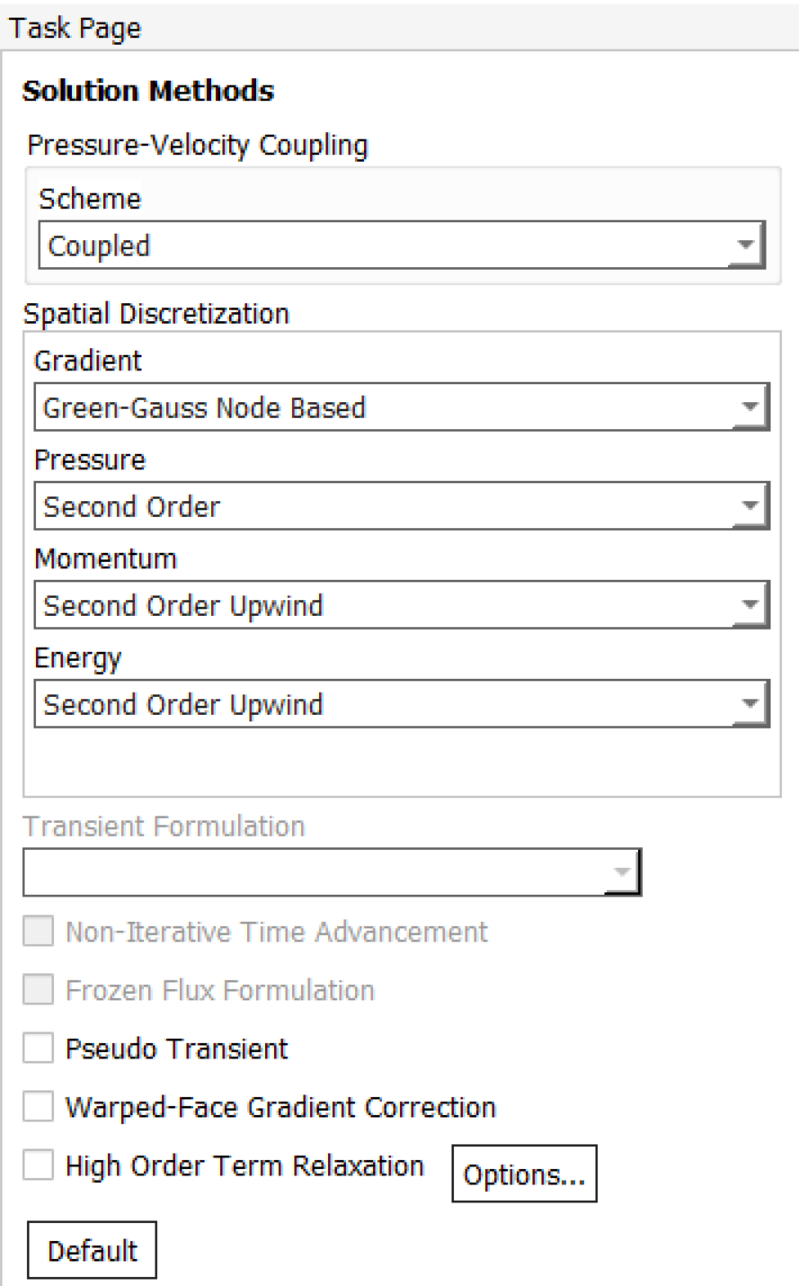
  In the solution Methods, I used a coupled scheme and second order.
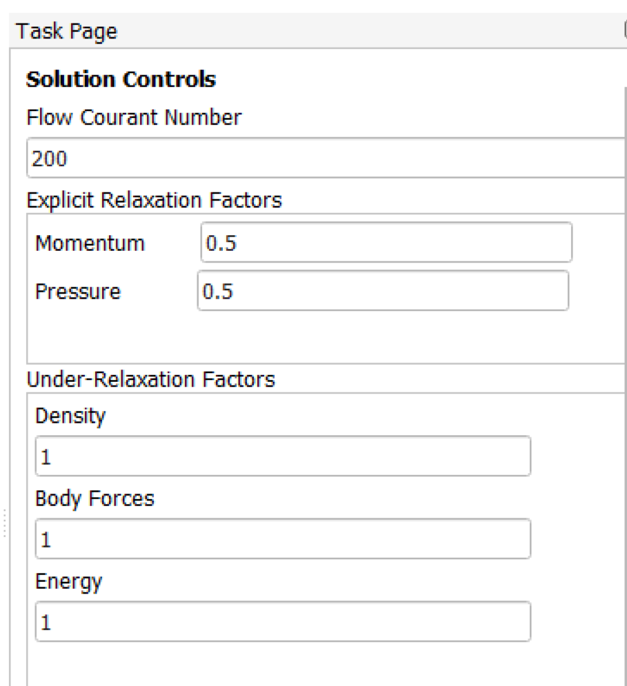
  The solution controls:
  The residuals are put (1e-6) and I applied Hybrid initialization. Then I run the simulation. The problem appears in the residual report, I didn't get a convergence at all.
 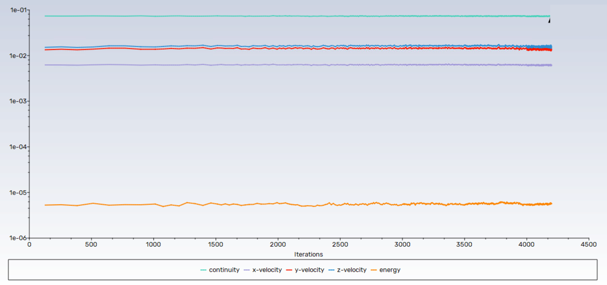 any help will be highly appreciated.
 -
October 3, 2024 at 1:33 pm
Rob
Forum ModeratorWhy would you expect mesh interfaces? What is the air density, and how do the energy fluxes and flow/temperature contours look?
-
October 3, 2024 at 2:40 pm
hasan.mustafa.moayad
Subscriberdear Rob, thank you for your reply.
as I know the mesh interfaces appear when there are interfaces between domains and this will lead to conjugated heat transfer. However, I made all bodies as one part in the design modeler and made share topology for that part. So, I suppose that I have conjugated heat transfer.
Air properties are defined by Ansys fluent, I didn’t make any changes.
I have one value of heat flux which is applied on the top surface of absorber domain.
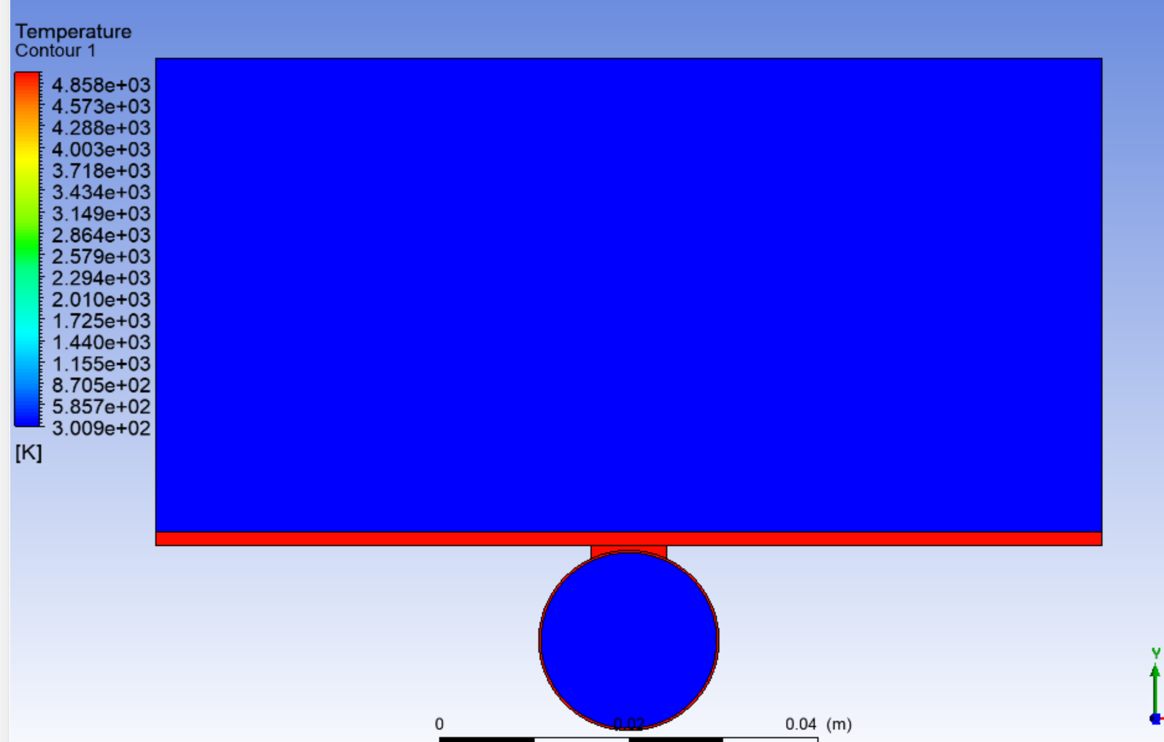
the temperature contour for all domains at a plane located at the inlet and outlet is the same (i.e. there are no differences between the two contours):
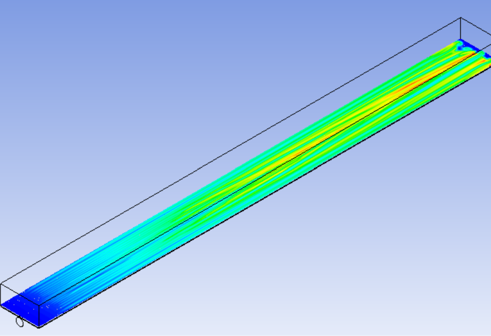
the temperature contour at a plane located nearly in the center of the air domain:
-
October 3, 2024 at 2:43 pm
Rob
Forum ModeratorYes, you should have wall and wall:shadow pairs. I assume you didn't alter the "coupled" setting?
If all properties are unchanged, what would cause motion in the fluid region?
-
October 3, 2024 at 3:43 pm
hasan.mustafa.moayad
Subscriberdear Rob,
I never changed the coupled setting.
the motion is due to inlet mass flow rate for both air and water.
-
October 3, 2024 at 4:05 pm
Rob
Forum ModeratorOK, so fully forced convection.
And the second image has appeared too.... Looks OK from what I can see. But, how well resolved is the mesh? How to all of the flux balances and monitor points look?
-
October 3, 2024 at 4:29 pm
hasan.mustafa.moayad
Subscriberdear Rob, I didn't get you, what do you mean by this : "But, how well resolved is the mesh? How to all of the flux balances and monitor points look?"
-
October 3, 2024 at 4:34 pm
Rob
Forum ModeratorYour residuals aren't great, but residuals aren't the only measure of convergence: monitors and fluxes also need to be checked. Similarly you showed a cross section of the mesh, but not how it looks in the third dimension: have you resolved any and all gradients?
-
October 3, 2024 at 5:22 pm
hasan.mustafa.moayad
SubscriberI have read some comments from other posts about the convergence and I have learned that not only the residuals can be used as a measure of convergence.
in my case, I didn't plot any results alongside the residual plot.
-
October 4, 2024 at 9:21 am
hasan.mustafa.moayad
Subscriberdear Rob,
could you please give me more advise?
thanks
-
October 4, 2024 at 10:45 am
Rob
Forum ModeratorBumping threads after about 14 hours is unnecessary - staff work office hours based on location, so response times will vary.
If you've not plotted the flux & monitor data you may want to investigate that. That may require you to run the model on.
The hot streaks in the second plot don't make much sense, hence comments regarding the convergence.
-
- You must be logged in to reply to this topic.


-
4663
-
1545
-
1386
-
1230
-
1021

© 2025 Copyright ANSYS, Inc. All rights reserved.

