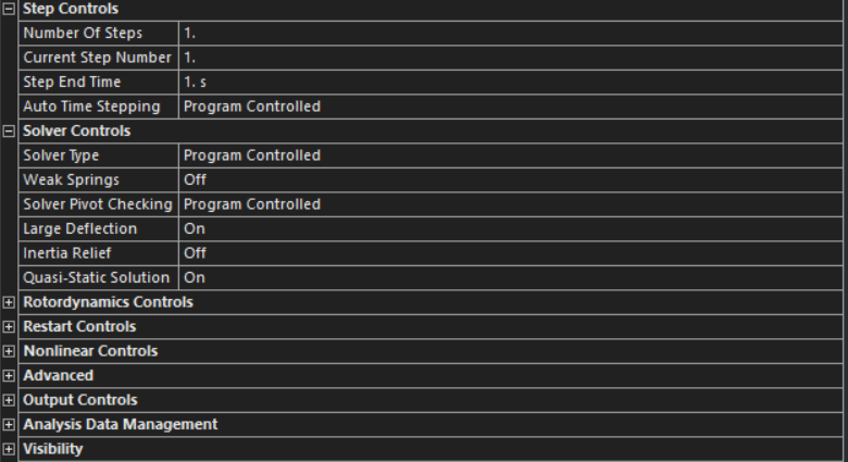
I'm trying to simulate a tensile test performed on a simple 6 layer rectangular Woven Carbon-epoxy composite specimen on a gauge length of 100mm, width 25mm. Have defined material properties using ACP (rosette and oriented selection set etc) and transferred shell composite data to the static structural system. Below is a picture of my analysis settings.
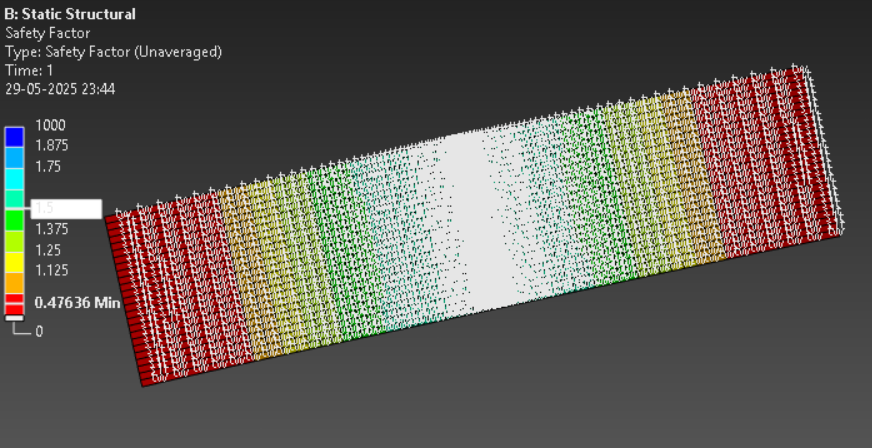
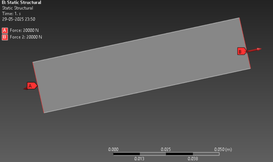
I have applied load on both ends of just 20kN (25.6kN was around the max force at failure in the experiment) (have tried appying this load as Force, Remote force 50mm away from edge, and as line pressure), and was expecting to find failure in the middle of the gauge section as desired/proven in the experiments. However the failure developed on the edges of the gauge section. Moreover the Failure occurs even at 20kN. How do I change setup and analysis settings to more accurately model the experiment? Will introducing loading steps change the outcome? My failure criteria are Max Stress, Max Strain and Tsai Wu
In the actual experiment, the full specimen size was 300mm, and 100mm in each side was clamped to the utm's arms, leaving a gauge length of 100mm. Of 5 samples, two did break along the edges, but 3 broke in the middle, could this simply be due to manufacturing defects? (Wet layup+compression moulding). Even so, the defects should make the model predict a higher UTS rather than lower. What gives? How should I calibrate the material properties or change the setup (should i model the entire 300mm specimen)