-
-
November 28, 2023 at 12:06 pm
Lingesh Kumar
SubscriberHi,
I would like to ask about the steps in how one can simulate the rotational motion of a CFD model.
Context:
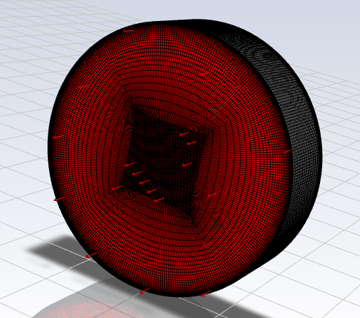
Geometrically the well plate model has a diameter of 34.8mm and a total height of 10mm. The medium inside is of a height of 2mm.I have made a O-grid structured mesh representing a well plate that I have added resolution to the base and wall through a combination of adding a bias factor from the edge of the wall radially moving towards the centre and adding inflation layers from the base of the well plate toward the center. I am sufficiently certain the mesh itself is of good quality. This is important for the context of collecting wall shear stress at the edge and base of the well plate.
Nodes: 492,280
Elements: 471,630
Aspect ratio: 3.4165 average (follows the recommended < 5, but is expected due to inflation layers)
Skewness: 0.02715 average (relatively close to 0)
Orthogonal quality: 0.9917 average (relatively close to 1)
The model follows a VOF model with laminar flow consisting of 2 fluid phases of the liquid medium and air with the respective dynamic viscosity and density (0.78e-03 Kg/ms and 1003 Kg/m3 for the liquid meidum and 1.8688e-05 Kg/ms and 1.1115 Kg/m3 for air). The solid is modelled as the standard aluminium in the Ansys library with a density of 2719 Kg/m3.
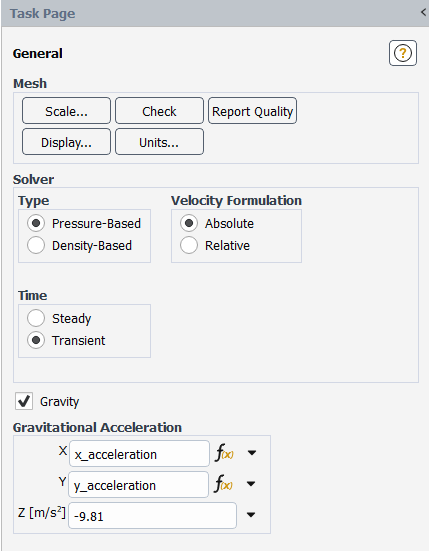
Named expressions for the X and Y domains have already been created and the Z domain follows gravity (-9.81m/s2) and applied accordingly.
The original experiment as shown by the image below shows that the the orbital shaking motion follows an orbital radius, a, of 5mm and an angular velocity, ω, of 150rpm (or 15.707963 rad/s). How would i simulate the swirling motion with these 2 parameters during the setup phase of Ansys.
Question 1: I believe this can be done in the Cell Zone conditions tab but I am unsure as to how to do this?
Context:
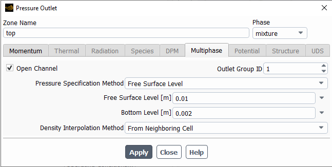
The model also has 2 main boundary conditions with the wall (named selections: wall) having a no-slip condition and the outlet (named selections: top) being set as a pressure outlet. A free surface level method is used with the specifications of the total well plate height and fluid medium height below:
Question 2: Is the Inlet boundary condition required? as the inlet currency is set as the (named seletions: base) which is not accurate from the orbital shaking experiment. I believe the liquid medium should already be inside the well plate and not coming through an inlet. Do i have to change this to an inteface in the boundary conditions?
-
November 28, 2023 at 3:18 pm
Rob
Forum ModeratorThe problem with the rotational set up is you need a rotating zone that's also rotating relative to a second axis. The slower speed equivalent would be a fair ground ride (Google "waltzer ride"). Fortunately Fluent has rotating options for absolute and relative reference frames, so we can cheat by using the fluid domain that you have, and by adding a solid block of a few cells to act as the other rotation zone: the fluid spins on it's own axis relative to the solid that rotates in the absolute reference frame.
-
March 15, 2024 at 6:34 am
Lingesh Kumar
SubscriberThank you! I have managed to solve it through a named expression modelling the inertial forces. Nonetheless, I have marked the question as answered!
-
May 20, 2024 at 2:36 am
jonnathan.aguilar
SubscriberHello Lingesh Kumar, I have the same problem, could you tell me how you solved it?
thank you -
May 20, 2024 at 4:53 am
Lingesh Kumar
SubscriberHi JonnathanAguilar,
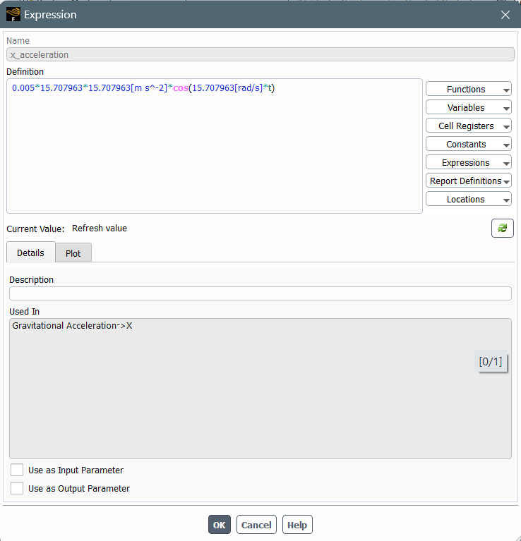
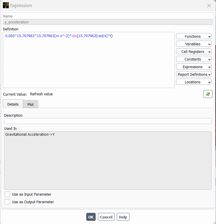
The particular named expression is taken from Alpresa’s paper (2017) whereby she defines an ingenious equation for the inertial forces for the x-direction (ex) and y-direction (ey) forces below; whereby the α represents the angular velocity, ω represents the orbital radius, The z-direction as you would expect follows that of gravity (-9.81 m/s2) and is therefore not seen in the equation but rather just manually input in the named expression. :
For more information, you can check the paper out:Alpresa, P. (2017) Fluid Dynamics of orbitally shaken shallow fluid layers. dissertation. Imperial College London.
with regards.
Lingesh Kumar -
May 21, 2024 at 2:03 am
jonnathan.aguilar
SubscriberThanks for your answer, to enter fluent you need a UDF, I was trying with DEFINE_CG_MOTION, but I don't know how to go from the balance of forces.
-
May 21, 2024 at 2:39 am
Lingesh Kumar
SubscriberHi JonnathanAguilar,
In my case, a UDF under the User-Defined tab was not compulsory and I never used it for my model – to that end I cannot reliably help you in that regard. However, I can underline the steps I took to create the named expressions. The workflow is shown as Domain tab > Setup > New named expression > x_acceleration + y_acceleration > manually inputting the z_acceleration.Step 1:
Step 3:
Step 4:
Step 5:
I hope that clarifies what I had explained in my previous answer. Beyond the named expressions I would not be of much help in UDFs as I had not used them.
With regards,
Lingesh Kumar
-
May 21, 2024 at 2:56 am
jonnathan.aguilar
SubscriberIt has helped me a lot, thank you very much.
Jonnathan Aguilar
-
May 21, 2024 at 9:03 am
Rob
Forum ModeratorBrownie points all round - thank you Lingesh.
-
- The topic ‘Simulating an orbital shaker’ is closed to new replies.


-
4969
-
1645
-
1386
-
1242
-
1021

© 2026 Copyright ANSYS, Inc. All rights reserved.

