-
-
December 18, 2023 at 9:03 amJordi Lopez LeyvaSubscriber
How can I simulate the rotation of permitivity? I want to rotate a crystal from 001 to 111 into z axis, which will change the permitivity tensor of chi1 AND chi2. To do so, is it sufficient to use the "permitivity rotation" simulation object, and specify the rotation angles inside the "rotationgridattribute" and place addgridattribute("permittivity rotation") in a material? It is a bit unclear to me
-
January 8, 2024 at 10:08 amDimitris PolyzosAnsys Employee
Hello Jordi,Â
Your suggestion looks correct to me, as it is described in this article Permittivity-Rotation-Simulation-object. For further information please refer to this article: Tips-and-background-information-when-using-grid-attributes.
I hope I helped.
Kidn regards
Dimitris
-
January 8, 2024 at 10:24 amJordi Lopez LeyvaSubscriber
Hi Dimitiris,
Thank you for the reply. When implementing the above I don't see a change in E field due to electro-optic effects pockels. Is it possible that Permitivity-Rotation only changes the first order chi tensor, and not higher orders? Or do you know if something else could be wrong?
Kindest regards,
Jordi Lopez Leyva
-
-
January 8, 2024 at 4:10 pmDimitris PolyzosAnsys Employee
Hello Jordi,
I would be interested to send me some of your results to check the issue though. Normally, you should see the different RI at differenent orientations of the tensor with a RI monitor. Also, you could try to use a dielectric material and check the E field if it changes for various orientations, instead of a non-linear material. Next step would be to check with the non-linear material.
Lumerical FDTD can simulate diagonal nonlinear optics, on-axis anisotropy (diagonal), as long as you give the diagonal permittivity or refractive index. You can check this application example Harmonic-generation-with-a-chi2-material.
However, if you want to calculate the nonlinear material chi2 for off-axis anisotropy. Off diagonal terms such as ch_xyz, can not simulated when the anisotropic material is rotated, thus is might needed to apply the plugin material too. This is a bit complicated to conduct it though.
Â
I hope I helped.
Kind regards
Dimitris
-
January 12, 2024 at 2:02 pmJordi Lopez LeyvaSubscriber
-
January 15, 2024 at 10:49 amJordi Lopez LeyvaSubscriber
I would like to add that the refractive index monitor can't capture nonlinear refractive index changes. Regardsless, with the field monitor I don't observe a difference between rotated and unrotated E field distribution
-
-
-
January 15, 2024 at 4:00 pmDimitris PolyzosAnsys Employee
Hello Jordi,Â
To my knowledge, nonlinear effects can be captured from the index monitor. Nonlinear index material has a different refractive index for different wavelengths. In the photos below you can see that there is a small change when I change the wavelength (my material is not highly dependent in wavelength). Please try the same with your material set in your model and let me know if you see any changes in the RI while you change the wavlength.
Another characteristic of a material is the spatially varying index that monitor can capture as well. The following photo shows a spatially varying index.
Regarding the difference between rotated and unrotated E field, could you please share a result from your model? Please increase the mesh of your simulation and check if there is any difference. Coarse meshing might be a reason of not seeing details in field monitors. Please refer to these articles in order to get information about the non linear materials:
Flexible-Material-Plugin-Framework
Advanced-and-custom-optical-material-models-in-FDTD-and-MODE
I hope I helped. Please let me know if you have any queries I can help with.
Kind regards
Dimitris
-
January 15, 2024 at 4:29 pmJordi Lopez LeyvaSubscriber
Hi Dimitris,
Thank you for the reply. I believe the example you gave only applies for multiple wavelengths. In my case I'm currently only interested/using in 1550nm, which induces a change in index via Pockels as n1=1/2*r*n0^3*E.
Additionally, I figured out why my rotation was not working. When in a structure group, even if you remove the tick in the box "construction group" such that you can update you individual structure compenents, modifying the "grid attribute name" resets. So I placed my nonlinear material out of the structure group, and now it saved the attribute name.
rotated:Âunrotated:
However, I still can't figure out why my index monitor doesn't correcty display the induced refractive index change due to Pockels, despite the simulation taking it into account. Could it be a lack of numerical precision of the monitor?
-
January 15, 2024 at 4:44 pmDimitris PolyzosAnsys Employee
Hello Jordi,Â
Thanks for your reply and I am happy you could sort it out. "In my case I'm currently only interested/using in 1550nm, which induces a change in index via Pockels as n1=1/2*r*n0^3*E", I wasn't aware of that, howver the nonlinear material corresponds to multiple wavelength dependency of RI. Maybe you mean the spatial variation of the Ri, or I misunderstood it?Â
If you use the equation n1=1/2*r*n0^3*E and add it in the material tab and check the RI with an index monitor, you have no change of Ri, with index monitor? Could you please elaborate with some screenshots what results you get and how you define your model?
Kind regards
Dimitris
-
January 15, 2024 at 6:10 pmJordi Lopez LeyvaSubscriber
Hi Dimitris,
I indeed meant the spatial variation of RI, since at different points in space different E field magnitudes are present. You mentioned "f you use the equation n1=1/2*r*n0^3*E and add it in the material tab and check the RI with an index monitor", how can I add that expression into the material tab?
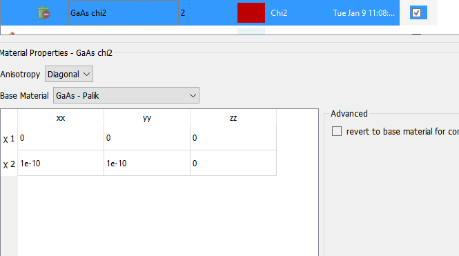
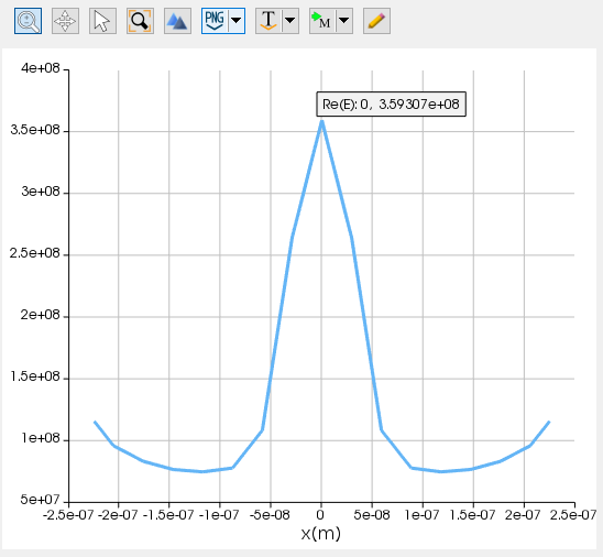
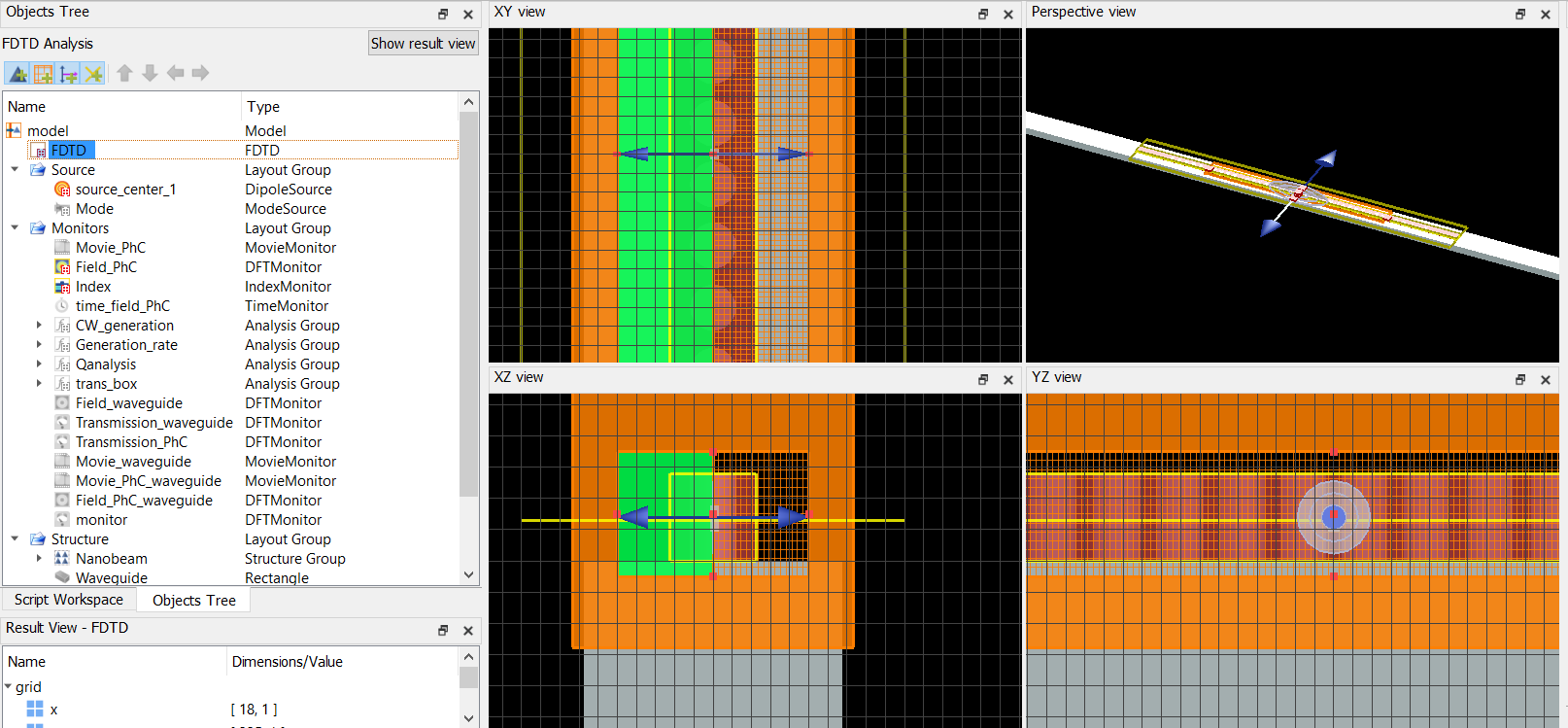
As for my model, I'm simulating 1D photonic crystal nanobeam made of GaAs (nonlinear using chi2=10^-10 model), with SiO2 as substrate, and surrounded by air. I'm using a dipole source at the center. FDTD is using standard PML mesh and symmetry.
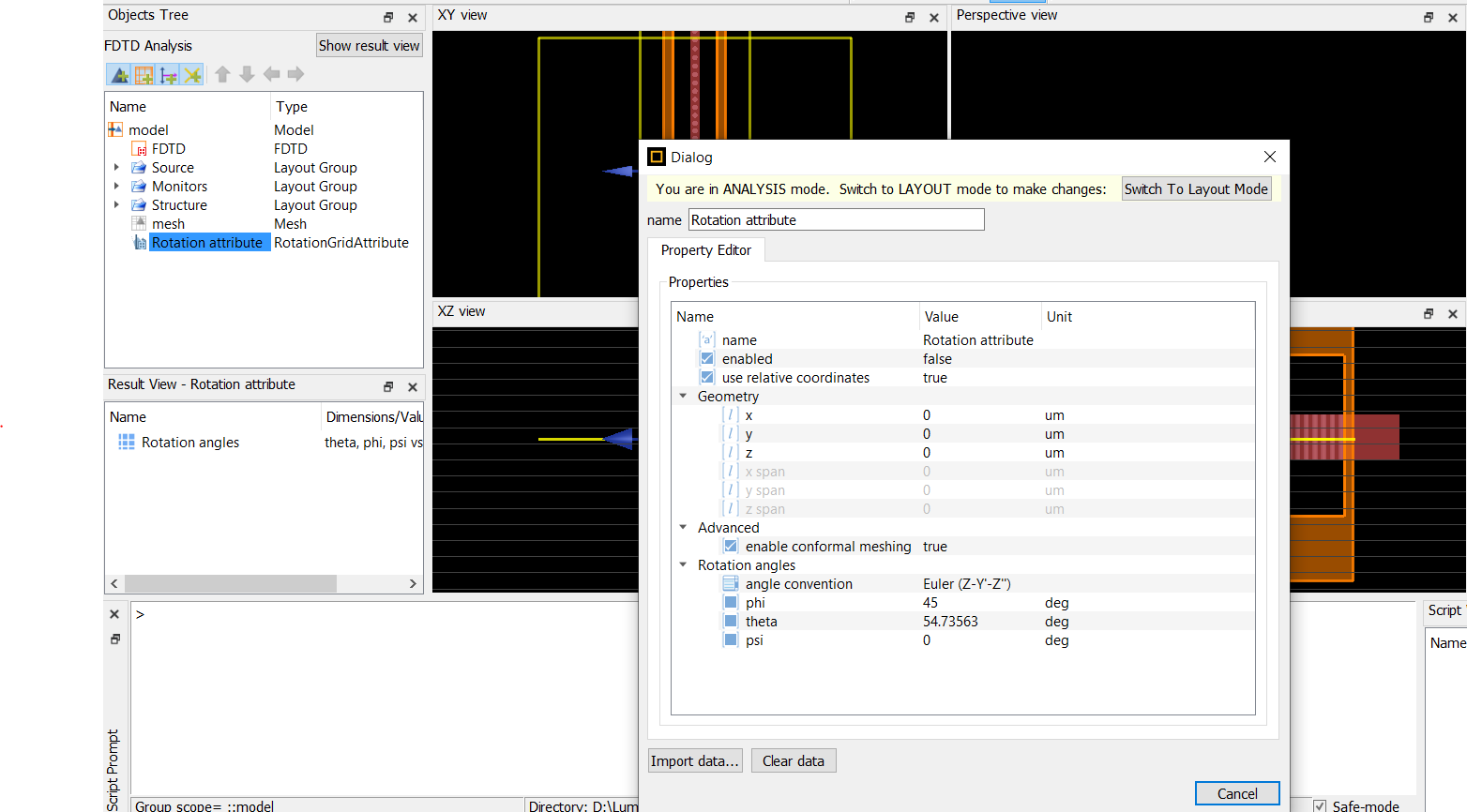
Â
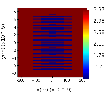
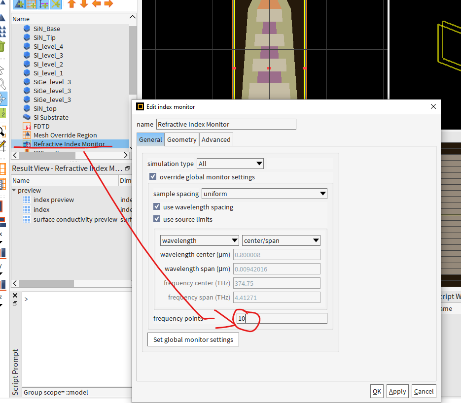
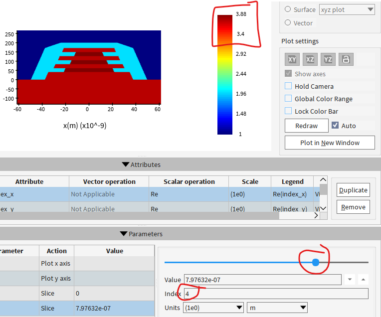
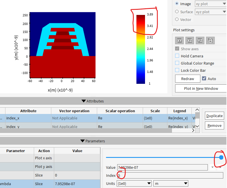
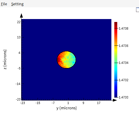
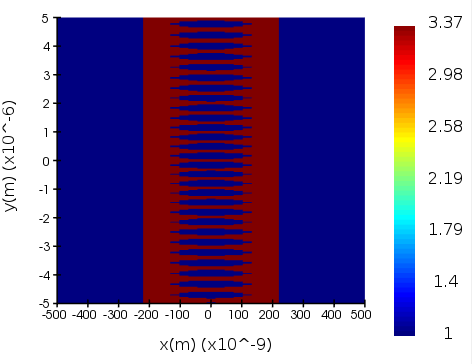
Refractive Index monitor:
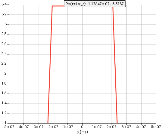
In 2nd plot you can see refractive index only goes to 3.3737 (This value is the same as first order refractive index without Pockels, despite Pockels being implemented in this result) no matter the amount of E field applied.
-
-
January 15, 2024 at 7:04 pmDimitris PolyzosAnsys Employee
Hello Jordi,Â
you can have a look in this article on how to add the equation with spatially varying index in the materil tab:
Step-index and graded-index fiber (FDE)
Also following this article's method you can add in the index material an equation where a spatially varying idex can be created:Specifying object properties with an equation and Spatially-varying-refractive-index-due-to-strain.
I hope I helped. Please let me know if you have any more queries on the above.
Kind regards
Dimitris
Â
-
January 16, 2024 at 1:45 pmJordi Lopez LeyvaSubscriber
Thank you Dimitris, I'll implement look into those examples
-
-
- The topic ‘Simulate anisotropy due to crystal orientation’ is closed to new replies.
- Difference between answers in version 2024 and 2017 lumerical mode solution
- Errors Running Ring Modulator Example on Cluster
- Import material .txt file with script
- Trapezoidal ring
- Help for qINTERCONNECT
- Absorption cross-section of AuNR excited by prism-based TIR
- Issues with getting result from interconnent analysis script
- How to measure transmission coefficients on a given plane .
- Topology Optimization Error
- Edge Coupler EME Example Issue
-
1882
-
802
-
599
-
591
-
366
© 2025 Copyright ANSYS, Inc. All rights reserved.